HP Unified Wired-WLAN Products IP Multicast Configuration Guide HP 830 Unified Wired-WLAN PoE+ Switch Series HP 850 Unified Wired-WLAN Appliance HP 870 Unified Wired-WLAN Appliance HP 11900/10500/7500 20G Unified Wired-WLAN Module Part number: 5998-4787 Software version: 3507P22 (HP 830 PoE+ Switch Series) 2607P22 (HP 850 Appliance) 2607P22 (HP 870 Appliance) 2507P22 (HP 11900/10500/7500 20G Module) Document version: 6W101-20140418
Legal and notice information © Copyright 2014 Hewlett-Packard Development Company, L.P. No part of this documentation may be reproduced or transmitted in any form or by any means without prior written consent of Hewlett-Packard Development Company, L.P. The information contained herein is subject to change without notice.
Contents Configuring IGMP snooping ······································································································································· 1 Overview············································································································································································ 1 Basic concepts in IGMP snooping ·························································································································· 2
Protocols and standards ······································································································································· 36 MLD snooping configuration task list ··························································································································· 36 Configuring basic MLD snooping functions ················································································································ 37 Configuration prerequisites
Port-based IPv6 multicast VLAN configuration task list ······························································································ 69 Configuring a port-based IPv6 multicast VLAN ·········································································································· 69 Configuration guidelines ······································································································································ 70 Configuration prerequisites ·············
Configuring IGMP snooping Overview IGMP snooping enables Layer 2 devices to establish Layer 2 multicast forwarding tables instead of flooding all multicast packets. To populate the Layer 2 multicast forwarding table, IGMP snooping listens to IGMP messages exchanged between a Layer 3 multicast device and hosts. By analyzing received IGMP messages, an IGMP snooping-enabled Layer 2 device establishes mappings between ports and multicast MAC addresses, and forwards multicast data based on these mappings.
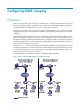
Basic concepts in IGMP snooping This section lists the basic concepts in IGMP snooping. IGMP snooping related ports As shown in Figure 2: • Router A connects to the multicast source. • IGMP snooping runs on Device A and Device B. • Host A and Host C are receiver hosts as members of a multicast group. Figure 2 IGMP snooping related ports As shown in Figure 2, IGMP snooping divides the ports on a Layer 2 device into the following types: • Router port—Layer 3 multicast device-side port.
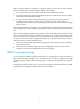
• Member port—GigabitEthernet 1/0/2 on the AC connects to a multicast receiver, so GigabitEthernet 1/0/2 is a member port. In addition, after an AP joins an ESS, the AC creates a virtual Layer 2 interface WLAN-DBSS associated with that ESS. As shown in Figure 3, after the AP joins two ESSs, the AC creates two virtual Layer 2 interfaces: WLAN-DBSS 67:67 and WLAN-DBSS 68:66. The ESS associated with WLAN-DBSS 67:67 contains a multicast receiver Client B, so WLAN-DBSS 67:67 is a member port.
How IGMP snooping works An IGMP snooping-enabled Layer 2 device performs different actions when it receives different IGMP messages. The ports in this section are dynamic ports. For information about how to configure and remove static ports, see "Configuring static ports." When receiving a general query The IGMP querier periodically sends IGMP general queries to all hosts and routers on the local subnet to determine whether any active multicast group members exist on the subnet.
After receiving an IGMP leave message on a dynamic member port, the Layer 2 device examines whether a forwarding entry matches the group address in the message. • If no match is found, the Layer 2 device directly discards the IGMP leave message. • If a match is found but the matching forwarding entry does not contain the port, the Layer 2 device directly discards the IGMP leave message.
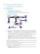
Figure 4 Network diagram As shown in Figure 4, AC works as an IGMP snooping proxy. As a host from the perspective of the querier Router A, AC represents its attached hosts to send membership reports and leave messages to Router A. Table 1 IGMP message processing on an IGMP snooping proxy IGMP message Actions General query When receiving an IGMP general query, the proxy forwards it to all ports except the port that receives the query.
Protocols and standards RFC 4541, Considerations for Internet Group Management Protocol (IGMP) and Multicast Listener Discovery (MLD) Snooping Switches IGMP snooping configuration task list For the configuration tasks in this section, the following rules apply: • The configurations made in IGMP-snooping view are effective on all VLANs. The configurations made in VLAN view are effective on only the current VLAN.
Task Remarks Enabling the IGMP snooping host tracking function Optional. Configuring basic IGMP snooping functions This section describes how to configure basic IGMP snooping functions. Configuration prerequisites Before you configure basic IGMP snooping functions, complete the following tasks: • Configure the associated VLANs. • Determine the version of IGMP snooping.
For more information about static joins, see "Configuring static ports." To specify the IGMP snooping version: Step Command Remarks 1. Enter system view. system-view N/A 2. Enter VLAN view. vlan vlan-id N/A 3. Specify the IGMP snooping version. igmp-snooping version version-number IGMPv2 snooping by default. Configuring IGMP snooping port functions This section describes how to configure IGMP snooping port functions.
Step Command Remarks 3. Set the aging timer for the dynamic router ports. igmp-snooping router-aging-time interval 105 seconds by default. 4. Set the aging timer for the dynamic member ports. igmp-snooping host-aging-time interval 260 seconds by default. Configuring static ports You can configure a port as a static port for the following purposes: • To make all the hosts attached to the port receive multicast data for a multicast group, configure the port as a static member port for the group.
Configuring a port as a simulated member host Generally, a host that runs IGMP can respond to IGMP queries. If a host fails to respond, the multicast router might consider that no member of this multicast group exists on the subnet. Then, it removes the associated forwarding entry. To avoid this situation, you can configure the port as a simulated member host for a multicast group. When the simulated member host receives an IGMP query, it gives a response.
Step Command Remarks 2. Enter IGMP-snooping view. igmp-snooping N/A 3. Enable IGMP snooping fast-leave processing. fast-leave [ vlan vlan-list ] Disabled by default. Enabling IGMP snooping fast-leave processing on a port Step 1. Enter system view. 2. Enter Layer 2 Ethernet interface view or Layer 2 aggregate interface view, or enter port group view.
Step Command Disable the port from becoming a dynamic router port. 3. igmp-snooping router-port-deny [ vlan vlan-list ] Remarks By default, a port can become a dynamic router port. This configuration does not affect the static router port configuration. Configuring IGMP snooping querier This section describes how to configure IGMP snooping querier. Configuration prerequisites Before you configure IGMP snooping querier, complete the following tasks: • Enable IGMP snooping in the VLAN.
Configuring parameters for IGMP queries and responses CAUTION: Make sure the interval for sending IGMP general queries is larger than the maximum response delay for IGMP general queries. Otherwise, multicast group members might be deleted by mistake. You can modify the IGMP general query interval based on actual condition of the network. A multicast listening host starts a timer for each multicast group that it has joined when it receives an IGMP query (general query or group-specific query).
problem, when an AC acts as the IGMP snooping querier, HP recommends that you configure a non-all-zero IP address as the source IP address of IGMP queries. Changing the source address of IGMP queries might affect the IGMP querier election within the subnet. To configure source IP addresses for IGMP queries: Step Command Remarks 1. Enter system view. system-view N/A 2. Enter VLAN view. vlan vlan-id N/A 3. Configure the source IP address for IGMP general queries.
Configuring the source IP addresses for the IGMP messages sent by the proxy You can set the source IP addresses for the IGMP reports and leave messages that the IGMP snooping proxy sends on behalf of its attached hosts. To configure the source IP addresses for the IGMP messages sent by the proxy in a VLAN: Step Command Remarks 1. Enter system view. system-view N/A 2. Enter VLAN view. vlan vlan-id N/A 3. Configure the source IP address for the IGMP reports that the proxy sends.
Configuring a multicast group filter globally Step Command Remarks 1. Enter system view. system-view N/A 2. Enter IGMP-snooping view. igmp-snooping N/A 3. Configure a multicast group filter globally. group-policy acl-number [ vlan vlan-list ] By default, no group filter is globally configured. That is, a host can join any valid multicast group. Configuring a multicast group filter on a port Step Enter system view. 1.
Step Enable dropping unknown multicast data globally. 3. Command Remarks drop-unknown Disabled by default. Enabling dropping unknown multicast data in a VLAN Step Command Remarks 1. Enter system view. system-view N/A 2. Enter VLAN view. vlan vlan-id N/A 3. Enable dropping unknown multicast data. igmp-snooping drop-unknown Disabled by default.
• If the port has been configured as a static member port of multicast groups, the system applies the configurations to the port again. • If you have configured simulated joining on the port, the system creates a forwarding entry for the port after receiving a report from the simulated member host. To set the maximum number of multicast groups that a port can join: Step 1. Enter system view. Command Remarks system-view N/A • Enter Layer 2 Ethernet interface 2.
Enabling multicast group replacement globally Step Command Remarks 1. Enter system view. system-view N/A 2. Enter IGMP-snooping view. igmp-snooping N/A 3. Enable multicast group replacement. overflow-replace [ vlan vlan-list ] Disabled by default. Enabling multicast group replacement on a port Step 1. Enter system view. Command Remarks system-view N/A • Enter Layer 2 Ethernet interface 2.
Step 3. Set the 802.1p precedence for IGMP messages in the VLAN. Command Remarks igmp-snooping dot1p-priority priority-number The default 802.1p precedence for IGMP messages is 0. Enabling the IGMP snooping host tracking function With the IGMP snooping host tracking function, the AC can record the information of the member hosts that are receiving multicast traffic. The member host information includes the host IP address, running duration, and timeout time.
Task Command Remarks Available in user view. Remove all the dynamic group entries of a specified IGMP snooping group or all IGMP snooping groups. reset igmp-snooping group { group-address | all } [ vlan vlan-id ] This command removes only dynamic group entries. Clear statistics for the IGMP messages learned through IGMP snooping. reset igmp-snooping statistics Available in user view. NOTE: The reset igmp group command cannot remove static IGMP group entries.
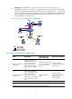
Figure 5 Network diagram Multicast Packets AC GE 2/0/1 Router A GE 2/0/2 Switch AP Source Client Configuration procedure 1. Configure WLAN services: # On the switch installed with the access controller module, log in to the configuration interface of the AC engine. oap connect slot 3 Press CTRL+K to quit. Connected to OAP! User interface aux0 is available. Press ENTER to get started. system-view # Create VLAN 100.
[AC-wlan-ap-ap-radio-1]radio enable [AC-wlan-ap-ap-radio-1]quit [AC-wlan-ap-ap]quit 2. Configure the wireless client to join the multicast group: # Enable IGMP snooping globally. [AC]igmp-snooping [AC-igmp-snooping]quit # Enable IGMP snooping in VLAN 100, and specify IGMPv3 snooping for the VLAN.
# Configure the client to access the WLAN service and request multicast traffic destined for 224.1.1.1. (Details not shown.) 3. Verify the configuration: # Display detailed IGMP snooping group information in VLAN 100 on AC. [AC]display igmp-snooping group vlan 100 verbose Total 1 IP Group(s). Total 1 IP Source(s). Total 1 MAC Group(s). Port flags: D-Dynamic port, S-Static port, C-Copy port, P-PIM port Subvlan flags: R-Real VLAN, C-Copy VLAN Vlan(id):100. Total 1 IP Group(s). Total 1 IP Source(s).
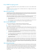
• Forward the queries to the hosts on behalf of Router A. Figure 6 Network diagram Configuration procedure 1. Assign an IP address and subnet mask to each interface, as shown in Figure 6. (Details not shown.) 2. Configure Router A: # Enable IP multicast routing, enable IGMP on Ethernet 1/1, and enable PIM-DM on each interface.
# Configure a WLAN service template with its SSID as Multicast and authentication method as open-system. Bind the WLAN-ESS interface with the service template. [AC]wlan service-template 1 clear [AC-wlan-st-1]ssid Multicast [AC-wlan-st-1]bind WLAN-ESS 1 [AC-wlan-st-1]authentication-method open-system [AC-wlan-st-1]service-template enable [AC-wlan-st-1]quit # Create AP template ap of model E-MSM460-WW, and configure its serial ID as CN2AD330S8.
# Configure GigabitEthernet 2/0/1 as a trunk port and its PVID as VLAN 100, and assign it to VLAN 100. [Device] interface GigabitEthernet 2/0/1 [Device-GigabitEthernet2/0/1] port link-type trunk [Device-GigabitEthernet2/0/1] port trunk pvid vlan 100 [Device-GigabitEthernet2/0/1] port trunk permit vlan 100 [Device-GigabitEthernet2/0/1] quit # Configure GigabitEthernet 2/0/2 as a trunk port, and assign it to VLAN 100.
# Display information about IGMP multicast groups on Router A. [RouterA] display igmp group Total 1 IGMP Group(s). Interface group report information of VPN-Instance: public net Ethernet1/1(10.1.1.1): Total 1 IGMP Group reported Group Address Last Reporter Uptime Expires 224.1.1.1 0.0.0.0 00:00:06 00:02:04 The output shows that Router A is maintaining the membership for the multicast group. # Send an IGMP leave message from Host A to leave the multicast group 224.1.1.1. (Details not shown.
Analysis IGMP snooping is not enabled. Solution 1. Use the display current-configuration command to view the running status of IGMP snooping. 2. If IGMP snooping is not enabled, use the igmp-snooping command in system view to enable IGMP snooping globally, and then use the igmp-snooping enable command in VLAN view to enable IGMP snooping for the VLAN. 3.
Configuring MLD snooping Overview MLD snooping is an IPv6 multicast constraining mechanism that runs on Layer 2 devices to manage and control IPv6 multicast groups. By analyzing received MLD messages, an MLD snooping-enabled AC establishes mappings between ports and multicast MAC addresses and forwards IPv6 multicast data based on these mappings. As shown in Figure 7, when MLD snooping is not running, IPv6 multicast packets are flooded to all wireless clients.
MLD snooping related ports As shown in Figure 8: • Router A connects to the multicast source. • MLD snooping runs on Device A and Device B. • Host A and Host C are receiver hosts (namely, members of an IPv6 multicast group). Figure 8 MLD snooping related ports As shown in Figure 8, MLD snooping divides the ports on Device A and Device B into the following types: • Router port—Layer 3 multicast device-side port. Layer 3 multicast devices include DRs and MLD queriers.
Figure 9 Port roles on an MLD snooping-enabled AC Aging timers for dynamic ports in MLD snooping Timer Description Expected message before expiration Action after expiration Dynamic router port aging timer When a port receives an expected message, the Layer 2 device starts an aging timer for the port. When the timer expires, the dynamic router port ages out. MLD general query with the source address other than 0::0 or IPv6 PIM hello message.
When receiving a general query The MLD querier periodically sends MLD general queries to all hosts and routers on the local subnet to determine whether any active IPv6 multicast group members exist on the subnet. All these hosts and routers are identified by the IPv6 multicast address FF02::1. After receiving an MLD general query, the Layer 2 device forwards it to all ports in the VLAN, except the port that received the query.
After receiving the MLD multicast-address-specific query, the Layer 2 device forwards the query through all its router ports in the VLAN and all member ports of the IPv6 multicast group. Then, it waits for the responding MLD reports from the directly connected hosts to check for the existence of members for the IPv6 multicast group.
MLD message Actions When receiving a report for an IPv6 multicast group, the proxy looks up the multicast forwarding table for the entry for the multicast group: • If a match is found and the matching entry contains the receiving port as a dynamic member port, the proxy restarts the aging timer for the port. • If a match is found but the matching entry does not contain the receiving port, the proxy adds the port to the forwarding entry as a dynamic member port.
Task Configuring MLD snooping port functions Configuring MLD snooping querier Configuring MLD snooping proxying Configuring an MLD snooping policy Remarks Configuring aging timers for dynamic ports Optional. Configuring static ports Optional. Configuring a port as a simulated member host Optional. Enabling MLD snooping fast-leave processing Optional. Disabling a port from becoming a dynamic router port Optional. Enabling MLD snooping querier Optional.
Step Command Remarks 1. Enter system view. system-view N/A 2. Enable MLD snooping globally and enter MLD-snooping view. mld-snooping Disabled by default. 3. Return to system view. quit N/A 4. Enter VLAN view. vlan vlan-id N/A 5. Enable MLD snooping for the VLAN. mld-snooping enable Disabled by default.
Configuring aging timers for dynamic ports If the memberships of IPv6 multicast groups change frequently, you can set a relatively small value for the aging timer of the dynamic member ports. If the memberships of IPv6 multicast groups change rarely, you can set a relatively large value. Setting the global aging timers for dynamic ports Step Command Remarks 1. Enter system view. system-view N/A 2. Enter MLD-snooping view. mld-snooping N/A 3. Set the global aging timer for dynamic router ports.
Step Enter system view. 1. Command Remarks system-view N/A • Enter Layer 2 Ethernet interface Enter Layer 2 Ethernet interface view or Layer 2 aggregate interface view or enter port group view. 2. view or Layer 2 aggregate interface view: interface interface-type interface-number Use either method. • Enter port group view: port-group manual port-group-name 3. Configure the port as a static member port.
NOTE: Unlike a static member port, a port configured as a simulated member host ages out like a dynamic member port. Enabling MLD snooping fast-leave processing The fast-leave processing feature enables the AC to process MLD done messages quickly. When the AC receives an MLD done message on a port, it immediately removes that port from the forwarding entry for the multicast group specified in the message.
MLD general queries and IPv6 PIM hello messages from the host affect the multicast routing protocol state on Layer 3 devices, such as the MLD querier or DR election. This might further cause network interruption. • To solve these problems, you can disable a port from becoming a dynamic router port after the port receives an MLD general query or IPv6 PIM hello message. This configuration also enhances network security and the control over multicast users.
multicast devices, you can configure the Layer 2 device as an MLD snooping querier. In this way, the Layer 2 device sends MLD queries, and establishes and maintains multicast forwarding entries. Do not configure an MLD snooping querier in an IPv6 multicast network that runs MLD. An MLD snooping querier does not participate in MLD querier elections. However, it might affect MLD querier elections because it sends MLD general queries with a low source IPv6 address.
Step Command Remarks 2. Enter VLAN view. vlan vlan-id N/A 3. Set the interval for sending MLD general queries. mld-snooping query-interval interval 125 seconds by default. 4. Set the maximum response delay for MLD general queries. mld-snooping max-response-time interval 10 seconds by default. Set the MLD last-listener query interval. mld-snooping last-listener-query-interval interval 1 second by default. 5.
Step Command Remarks 1. Enter system view. system-view N/A 2. Enter VLAN view. vlan vlan-id N/A 3. Enable MLD snooping proxying in the VLAN. mld-snooping proxying enable Disabled by default. Configuring the source IPv6 addresses for the MLD messages sent by the proxy You can set the source IPv6 addresses of the MLD reports and done messages that the MLD snooping proxy sends on behalf of its attached hosts.
passes the ACL filtering, the AC adds the receiving port to the entry. Otherwise, the AC drops this report message. In this case, the IPv6 multicast data for the IPv6 multicast group is not sent to this port, and the user cannot retrieve the program. Configuring an IPv6 multicast group filter globally Step Command Remarks 1. Enter system view. system-view N/A 2. Enter MLD-snooping view. mld-snooping N/A 3. Configure an IPv6 multicast group filter.
Enabling dropping unknown IPv6 multicast data globally Step Command Remarks 1. Enter system view. system-view N/A 2. Enter MLD-snooping view. mld-snooping N/A 3. Enable dropping unknown IPv6 multicast data. drop-unknown Disabled by default. Support for this command depends on your device model. Enabling dropping unknown IPv6 multicast data in a VLAN Step Command Remarks 1. Enter system view. system-view N/A 2. Enter VLAN view. vlan vlan-id N/A 3.
When you configure this maximum number on a port, follow these guidelines: • If the number of IPv6 multicast groups the port has joined exceeds the configured maximum value, the system deletes all the forwarding entries for the port from the MLD snooping forwarding table. The receiver hosts on this port need to join IPv6 multicast groups again. When the number of IPv6 multicast groups reaches the maximum value, the receiver hosts on this port cannot join any other IPv6 multicast groups.
Enabling IPv6 multicast group replacement globally Step Command Remarks 1. Enter system view. system-view N/A 2. Enter MLD-snooping view. mld-snooping N/A 3. Enable IPv6 multicast group replacement. overflow-replace [ vlan vlan-list ] Disabled by default. Enabling IPv6 multicast group replacement on a port Step 1. Enter system view. Command Remarks system-view N/A • Enter Layer 2 Ethernet interface 2.
Enabling the MLD snooping host tracking function With the MLD snooping host tracking function, the AC can record the information of the member hosts that are receiving IPv6 multicast traffic. The member host information includes the host IPv6 address, running duration, and timeout time. Based on the recorded information, you can monitor and manage the member hosts. Enabling the MLD snooping host tracking function globally Step Command Remarks 1. Enter system view. system-view N/A 2.
NOTE: The reset mld-snooping group command cannot remove static MLD group entries. MLD snooping configuration examples This section provides examples of configuring MLD snooping. Multicast delivery to a wireless client The configuration examples were created on the 11900/10500/7500 20G unified wired-WLAN module and might vary with device models.
Press CTRL+K to quit. Connected to OAP! User interface aux0 is available. Press ENTER to get started. system-view # Create VLAN 100. [AC]Vlan 100 [AC-vlan100]quit # Create interface WLAN-ESS 1, and assign it to VLAN 100. [AC]interface WLAN-ESS 1 [AC-WLAN-ESS1]port access vlan 100 [AC-WLAN-ESS1]quit # Configure a WLAN service template with its SSID as Multicast and authentication method as open-system. Bind the WLAN-ESS interface with the service template.
# Use the shortcut keys Ctrl + K to return to the configuration interface of the switching engine, and enable IGMP snooping globally. system-view [Device] mld-snooping [Device-mld-snooping] quit # Create VLAN 100, and enable MLD snooping in the VLAN. [Device] vlan 100 [Device-vlan100] mld-snooping enable [Device-vlan100] quit # Configure GigabitEthernet 2/0/1 as a trunk port and its PVID as VLAN 100, and assign it to VLAN 100.
WLAN-DBSS1:0 (D) ( 00:04:17 ) MAC group(s): MAC group address:3333-0000-0101 Host port(s):total 1 port(s). WLAN-DBSS1:0 The output shows that WLAN-DBSS1:0 on AC has joined the IPv6 multicast group FF1E::1. MLD snooping proxying configuration example The configuration examples were created on the 11900/10500/7500 20G unified wired-WLAN module and might vary with device models.
Figure 12 Network diagram Configuration procedure 1. Assign an IP address and subnet mask to each interface, as shown in Figure 12. (Details not shown.) 2. Configure Router A: # Enable IP multicast routing, enable MLD on Ethernet 1/1, and enable IPv6 PIM-DM on each interface.
[AC-WLAN-ESS1]port access vlan 100 [AC-WLAN-ESS1]quit # Configure a WLAN service template with its SSID as Multicast and authentication method as open-system. Bind the WLAN-ESS interface with the service template. [AC]wlan service-template 1 clear [AC-wlan-st-1]ssid Multicast [AC-wlan-st-1]bind WLAN-ESS 1 [AC-wlan-st-1]authentication-method open-system [AC-wlan-st-1]service-template enable [AC-wlan-st-1]quit # Create AP template ap of model E-MSM460-WW, and configure its serial ID as CN2AD330S8.
# Configure GigabitEthernet 2/0/1 as a trunk port and its PVID as VLAN 100, and assign it to VLAN 100. [Device] interface GigabitEthernet 2/0/1 [Device-GigabitEthernet2/0/1] port link-type trunk [Device-GigabitEthernet2/0/1] port trunk pvid vlan 100 [Device-GigabitEthernet2/0/1] port trunk permit vlan 100 [Device-GigabitEthernet2/0/1] quit # Configure GigabitEthernet 2/0/2 as a trunk port, and assign it to VLAN 100.
# Display information about MLD multicast groups on Router A. [RouterA] display mld group Total 1 MLD Group(s). Interface group report information Ethernet1/1(2001::1): Total 1 MLD Group reported Group Address: FF1E::1 Last Reporter: FE80::2FF:FFFF:FE00:1 Uptime: 00:00:03 Expires: 00:04:17 The output shows that Router A is maintaining the membership for the IPv6 multicast group. # Send an MLD done message from Host A to leave the IPv6 multicast group FF1E::1. (Details not shown.
Layer 2 multicast forwarding cannot function Symptom Layer 2 multicast forwarding cannot function. Analysis MLD snooping is not enabled. Solution 1. Use the display current-configuration command to view the running status of MLD snooping. 2. If MLD snooping is not enabled, use the mld-snooping command to enable MLD snooping globally, and then use the mld-snooping enable command to enable MLD snooping in VLAN view. 3.
Configuring multicast VLANs Overview As shown in Figure 13, Host A, Host B, and Host C reside in three different VLANs and join the same multicast group. When Router A (Layer 3 device) receives multicast data for that group, it sends three copies of the data to AC (Layer 2 device). This occupies large bandwidth and increases the burden of the Layer 3 device.
Figure 14 Port-based multicast VLAN IGMP snooping manages the router ports and member ports in the multicast VLAN. When AC receives an IGMP message from a user port, it tags the message with the multicast VLAN ID and sends it to the IGMP querier. When Router A receives multicast data from the multicast source, it sends only one copy of the multicast data to the multicast VLAN on AC. Then, AC sends a separate copy of the multicast data to each sub-VLAN of the multicast VLAN.
• A user port can be configured as a multicast VLAN port only if it is an Ethernet port, a WLAN-ESS interface, or a Layer 2 aggregate interface. • In Ethernet interface view, WLAN-ESS interface view, or Layer 2 aggregate interface view, the configurations are effective only on the current port. In port group view, the configurations are effective on all ports in the current port group.
When you configure multicast VLAN ports, follow these guidelines: • Do not configure a multicast VLAN on a device with multicast routing enabled. • The VLAN to be configured as a multicast VLAN must exist. • A port cannot belong to multiple multicast VLANs. Adding user ports to the multicast VLAN Step Command Remarks 1. Enter system view. system-view N/A 2. Configure the specified VLAN as a multicast VLAN and enter multicast VLAN view.
Port-based multicast VLAN configuration example The configuration examples were created on the 11900/10500/7500 20G unified wired-WLAN module and might vary with device models. When configuring the 11900/10500/7500 20G unified wired-WLAN module, make sure the settings are correct (including VLAN settings) on the internal Ethernet interface that connects the module to the switch. For more information, see HP 11900/10500/7500 20G Unified Wired-WLAN Module Basic Configuration Guide.
[Router] multicast routing-enable [Router] interface ethernet 1/1 [Router-Ethernet1/1] pim dm [Router-Ethernet1/1] quit [Router] interface ethernet 1/2 [Router-Ethernet1/2] pim dm [Router-Ethernet1/2] igmp enable [Router-Ethernet1/2]quit 3. Configure AC: # On the configuration interface of the switching engine, enable IGMP snooping globally.
[AC-vlan3] quit # Create interface WLAN-ESS 1, and configure it as a hybrid port and VLAN 10 as the PVID. [AC] interface WLAN-ESS 1 [AC-WLAN-ESS1] port link-type hybrid [AC-WLAN-ESS1] port hybrid pvid vlan 10 # Assign WLAN-ESS 1 to VLAN 2, VLAN 3, and VLAN 10 as an untagged VLAN member. [AC-WLAN-ESS1] port hybrid vlan 2 3 10 untagged # Enable the MAC-based VLAN feature on WLAN-ESS 1. [AC-WLAN-ESS1] mac-vlan enable # Associate MAC addresses of Client A and Client B with VLAN 2 and VLAN 3, respectively.
[Switch-Ethernet1/2] quit 5. Verify the configuration: # Display the multicast VLAN information on AC. [AC] display multicast-vlan Total 1 multicast-vlan(s) Multicast vlan 10 port list: WLAN-ESS 1 # Display the IGMP snooping multicast group information on AC. [AC] display igmp-snooping group Total 1 IP Group(s). Total 1 IP Source(s). Total 1 MAC Group(s). Port flags: D-Dynamic port, S-Static port, C-Copy port, P-PIM port Subvlan flags: R-Real VLAN, C-Copy VLAN Vlan(id):10. Total 1 IP Group(s).
Configuring IPv6 multicast VLANs Overview As shown in Figure 16, Host A, Host B, and Host C reside in different VLANs and join the same IPv6 multicast group. When Router A (Layer 3 device) receives IPv6 multicast data for that group, it forwards three copies of the data to AC (Layer 2 device). This occupies large bandwidth and increases the burden on the Layer 3 device.
Figure 17 Port-based IPv6 multicast VLAN MLD snooping manages the router ports and member ports in the IPv6 multicast VLAN. When AC receives an MLD message from a user port, it tags the message with the IPv6 multicast VLAN ID and sends it to the MLD querier. When Router A receives the IPv6 multicast data, it sends only one copy of the IPv6 multicast data to the IPv6 multicast VLAN on AC. Then, AC sends a separate copy to each member port in the IPv6 multicast VLAN.
Configuration guidelines When you configure port-based IPv6 multicast VLANs, follow these guidelines: • You must first configure a VLAN as an IPv6 multicast VLAN, and configure the attributes of each user port. Then, you can assign the ports to the IPv6 multicast VLAN. • A user port can be configured as a multicast VLAN interface only if it is an Ethernet port, a WLAN-ESS interface, or a Layer 2 aggregate interface.
For more information about the port link-type, port hybrid pvid vlan, and port hybrid vlan commands, see Layer 2 Command Reference. Configuring IPv6 multicast VLAN ports In this method, configure a particular VLAN as an IPv6 multicast VLAN and assign user ports to this IPv6 multicast VLAN. When you configure IPv6 multicast VLAN ports, follow these guidelines: • Do not configure an IPv6 multicast VLAN on a device with multicast routing enabled.
IPv6 multicast VLAN configuration examples This section provides examples of configuring IPv6 multicast VLAN. Port-based multicast VLAN configuration example The configuration examples were created on the 11900/10500/7500 20G unified wired-WLAN module and might vary with device models. When configuring the 11900/10500/7500 20G unified wired-WLAN module, make sure the settings are correct (including VLAN settings) on the internal Ethernet interface that connects the module to the switch.
2. Configure Router: # Enable IPv6 multicast routing, enable IPv6 PIM-DM on each interface, and enable MLD on the AC-side interface Ethernet 1/2. system-view [Router] multicast ipv6 routing-enable [Router] interface ethernet 1/1 [Router-Ethernet1/1] pim ipv6 dm [Router-Ethernet1/1] quit [Router] interface ethernet 1/2 [Router-Ethernet1/2] pim ipv6 dm [Router-Ethernet1/2] mld enable [Router-Ethernet1/2] quit 3.
[AC] mac-vlan mac-address A6-5B-89 vlan 3 # Enable MLD snooping in VLAN 2 and VLAN 3. [AC] vlan 2 [AC-vlan2] mld-snooping enable [AC-vlan2] quit [AC] vlan 3 [AC-vlan3] mld-snooping enable [AC-vlan3] quit # Configure VLAN 10 as an IPv6 multicast VLAN. [AC] multicast-vlan ipv6 10 # Assign WLAN-ESS 1 to IPv6 multicast VLAN 10. [AC-ipv6-mvlan-10] port WLAN-ESS 1 [AC-ipv6-mvlan-10] quit 4. Verify the configuration: # Display the IPv6 multicast VLAN information on AC.
Support and other resources Contacting HP For worldwide technical support information, see the HP support website: http://www.hp.
Conventions This section describes the conventions used in this documentation set. Command conventions Convention Description Boldface Bold text represents commands and keywords that you enter literally as shown. Italic Italic text represents arguments that you replace with actual values. [] Square brackets enclose syntax choices (keywords or arguments) that are optional. { x | y | ... } Braces enclose a set of required syntax choices separated by vertical bars, from which you select one.
Network topology icons Represents a generic network device, such as a router, switch, or firewall. Represents a routing-capable device, such as a router or Layer 3 switch. Represents a generic switch, such as a Layer 2 or Layer 3 switch, or a router that supports Layer 2 forwarding and other Layer 2 features. Represents an access controller, a unified wired-WLAN module, or the switching engine on a unified wired-WLAN switch. Represents an access point.
Index CDEIMOPRT C I Configuring a port-based IPv6 multicast VLAN,69 IGMP snooping configuration examples,22 Configuring a port-based multicast VLAN,61 IGMP snooping configuration task list,7 Configuring an MLD snooping policy,45 IPv6 multicast VLAN configuration examples,72 Configuring basic IGMP snooping functions,8 M Configuring basic MLD snooping functions,37 MLD snooping configuration examples,51 Configuring IGMP snooping policies,16 MLD snooping configuration task list,36 Configuring IGMP