HP Unified Wired-WLAN Products Layer 2 Command Reference HP 830 Unified Wired-WLAN PoE+ Switch Series HP 850 Unified Wired-WLAN Appliance HP 870 Unified Wired-WLAN Appliance HP 11900/10500/7500 20G Unified Wired-WLAN Module Part number: 5998-4788 Software version: 3507P22 (HP 830 PoE+ Switch Series) 2607P22 (HP 850 Appliance) 2607P22 (HP 870 Appliance) 2507P22 (HP 11900/10500/7500 20G Module) Document version: 6W101-20140418
Legal and notice information © Copyright 2014 Hewlett-Packard Development Company, L.P. No part of this documentation may be reproduced or transmitted in any form or by any means without prior written consent of Hewlett-Packard Development Company, L.P. The information contained herein is subject to change without notice.
Contents Ethernet interface configuration commands ··············································································································· 1 General Ethernet interface configuration commands ···································································································· 1 combo enable ··························································································································································· 1 default ···············
port hybrid pvid ····················································································································································· 47 port hybrid vlan ····················································································································································· 48 port link-type ·························································································································································· 49
pppoe-server log-information off ·························································································································· 94 pppoe-server max-sessions local-mac ·················································································································· 94 pppoe-server max-sessions remote-mac ·············································································································· 95 pppoe-server max-sessions total ················
Ethernet interface configuration commands General Ethernet interface configuration commands combo enable Use combo enable to activate the copper or fiber combo port of a combo interface. Syntax combo enable { copper | fiber } Default The copper combo port of a combo interface is activated. Views Ethernet interface view (combo interface) Default command level 2: System level Parameters copper: Activates the copper combo port. In this case, use twisted pairs to connect the port.
default Use default to restore the default settings for an Ethernet interface. Syntax default Views Ethernet interface view Default command level 2: System level Usage guidelines CAUTION: The default command might interrupt ongoing network services. Make sure you are fully aware of the impacts of this command when you use it in a live network. This command might fail to restore the default settings for some commands for reasons such as command dependencies and system restrictions.
Parameters text: Specifies the interface description, a case-sensitive string of 1 to 80 characters. When you specify a description, follow these guidelines: • Each Unicode character takes the space of two regular characters. • To use Unicode characters or symbols in an interface description, install a specific IME and log in to the device through remote login software that supports the character type.
regular-expression: Specifies a regular expression, a case-sensitive string of 1 to 256 characters. Usage guidelines If no interface type is specified, this command displays information about all interfaces. If an interface type is specified but no interface number is specified, this command displays information about all interfaces of the specified type. Examples # Display detailed information about Layer 2 interface Ten-GigabitEthernet 1/0/1.
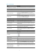
Table 1 Command output Field Description GigabitEthernet1/0/1 current state Physical state of the Ethernet interface. For more information, see Table 2. IP Packet Frame Type Ethernet framing format on the interface. Loopback Loopback testing status of the interface. The interface is operating at 1000 Mbps. 1000Mbps-speed mode This field displays Unknown-speed mode when the interface is disconnected from the peer with which it will automatically negotiate a port speed.
Field Input (total): 21322 packets, 1748554 bytes 68235 unicasts, 4718 broadcasts, 7852 multicasts, - pauses Input (normal): 21322 packets, bytes 1268 unicasts, 7560 broadcasts, 12494 multicasts, 0 pauses Description Inbound traffic statistics (in packets and bytes) for the interface. All inbound normal and abnormal packets (including unicast, broadcast, and multicast), and pause frames were counted.
Field Description ignored Number of inbound frames dropped because the receive buffer of the port ran low. - parity errors Total number of frames with parity errors. Output (total): 1502 packets, 138924 bytes - unicasts, 2 broadcasts, 406 multicasts, 0 pauses Output (normal): - packets, - bytes 1094 unicasts, - broadcasts, multicasts, - pauses Outbound traffic statistics (in packets and bytes) for the port.
Field Description DOWN ( OAM connection failure ) The interface is down because an OAM connection failed to be established on it or the OAM connection is disconnected. DOWN ( DLDP connection failure ) The interface is down because a DLDP connection failed to be established on it or the DLDP connection is disconnected. DOWN ( Loopback detection-protected ) The interface is shut down because a loop is detected on it. DOWN ( BPDU-protected ) The interface is shut down by the BPDU guard function.
XGE1/0/2 ADM auto F A 1 When you use the begin keyword to filter the output, the system only searches the Layer 2 interface list. # Display brief information about all UP interfaces. display interface brief | include UP The brief information of interface(s) under route mode: Link: ADM - administratively down; Stby - standby Protocol: (s) - spoofing Interface Link Protocol Main IP M-GE1/0/0 UP UP 192.168.11.8 Description NULL0 UP UP(s) -- Vlan1 UP UP 192.168.0.
Table 3 Command output Field Description The brief information of interface(s) under route mode: The command displays brief information about Layer 3 interfaces. Link layer state of the interface: Link: ADM administratively down; Stby - standby • ADM—The interface has been shut down by the network administrator. To recover its physical layer state, use the undo shutdown command. • Stby—The interface is a standby interface.
Field Description Duplex mode of the interface: Duplex • • • • • A—Autonegotiation. F—Full duplex. F(a)—Auto-negotiated full duplex. H—Half duplex. H(a)—Auto-negotiated half duplex. Link type of the interface: Type PVID • A—Access. • H—Hybrid. • T—Trunk. Port VLAN ID. Table 4 Causes for the physical state of an interface to be DOWN Field Description Not connected No physical connection exists (possibly because the network cable is disconnected or faulty).
Views Ethernet interface view Default command level 2: System level Parameters auto: Sets the interface to operate in autonegotiation mode. full: Sets the interface to operate in full duplex mode. Usage guidelines Support for this command varies with device models. For more information, see About the Command References for HP Unified Wired-WLAN Products. Examples # Configure interface Ten-GigabitEthernet 1/0/1 to operate in autonegotiation mode.
interface Use interface to enter interface view. Syntax interface interface-type interface-number Views System view Default command level 2: System level Parameters interface-type: Specifies an interface type. interface-number: Specifies an interface number. Examples # Enter Ten-GigabitEthernet 1/0/1 interface view (assuming that the interface is a Layer 2 Ethernet interface).
Usage guidelines In Ethernet interface view, this command applies only to the Ethernet interface. In port group view, this command applies to the Ethernet interfaces in the port group. Examples # Enable jumbo frames to pass through all Ethernet interfaces in port group group1.
reset counters interface Use reset counters interface to clear the Ethernet interface statistics. Syntax reset counters interface [ interface-type [ interface-number ] Views User view Default command level 2: System level Parameters interface-type: Specifies an interface type. interface-number: Specifies an interface number. Usage guidelines Clear old statistics on the interface before collecting new traffic statistics for a specific period of time.
Do not execute the shutdown command on the following interfaces: • The internal interface connecting the HP 11900/10500/7500 20G unified wired-WLAN module and the switch. • The internal interface connecting the HP 830 series PoE+ unified wired-WLAN switch or the HP 870 unified wired-WLAN appliance and the switching engine. Examples # Shut down and then bring up Ten-GigabitEthernet 1/0/1.
Layer 2 Ethernet interface configuration commands broadcast-suppression Use broadcast-suppression to set the broadcast suppression threshold on an Ethernet interface or a group of Ethernet interfaces. Use undo broadcast-suppression to restore the default broadcast suppression threshold. Syntax broadcast-suppression { ratio | pps max-pps } undo broadcast-suppression Default Ethernet interfaces do not suppress broadcast traffic.
Examples # Set the broadcast suppression threshold to 20% on Ten-GigabitEthernet 1/0/1. system-view [Sysname] interface Ten-gigabitethernet 1/0/1 [Sysname-Ten-GigabitEthernet1/0/1] broadcast-suppression 20 # Set the broadcast suppression threshold to 20% on all ports in the manual port group named group1.
group1 # Display detailed information about all port groups. display port-group manual all Member of group1: Ten-GigabitEthernet1/0/1 Ten-GigabitEthernet1/0/2 # Display detailed information about the port group named group1. display port-group manual name group1 Member of group1: Ten-GigabitEthernet1/0/1 Ten-GigabitEthernet1/0/2 group-member Use group-member to assign Ethernet interfaces to a port group. Use undo group-member to remove Ethernet interfaces from the port group.
multicast-suppression Use multicast-suppression to set the multicast suppression threshold on an Ethernet interface or a group of Ethernet interfaces. Use undo multicast-suppression to restore the default multicast suppression threshold. Syntax multicast-suppression { ratio | pps max-pps } undo multicast-suppression Default Ethernet interfaces do not suppress multicast traffic.
[Sysname-Ten-GigabitEthernet1/0/1] multicast-suppression 20 # Set the multicast threshold to 20% on all ports in the port group named group1. system-view [Sysname] port-group manual group1 [Sysname-port-group-manual-group1] group-member ten-gigabitethernet1/0/1 [Sysname-port-group-manual-group1] group-member ten-gigabitethernet1/0/2 [Sysname-port-group-manual-group1] multicast-suppression 20 port-group manual Use port-group manual to create a port group and enter port group view.
Views Layer 2 Ethernet interface view, port group view Default command level 2: System level Parameters ratio: Sets the unknown unicast suppression threshold as a percentage of the maximum interface rate. The value range for this argument is 1 to 100. The smaller the percentage, the less unknown unicast traffic is allowed to be received. pps max-pps: Specifies the maximum number of unknown unicast packets that the Ethernet interface can receive per second.
Loopback and null interface configuration commands default Use default to restore the default settings for the loopback or null interface. Syntax default Views Loopback interface view, null interface view Default command level 2: System level Usage guidelines CAUTION: The default command might interrupt ongoing network services. Make sure you are fully aware of the impacts of this command when you use it in a live network.
Default The description of a loopback or null interface is interface name Interface, for example, Loopback0 interface. Views Loopback interface view, null interface view Default command level 2: System level Parameters text: Specifies an interface description, a case-sensitive string of 1 to 80 characters. When you specify an interface description, follow these guidelines: • An interface description can be a mixture of English characters and other Unicode characters.
brief: Displays brief interface information. If you do not specify this keyword, the command displays detailed interface information. down: Displays information about interfaces in down state and the causes. If you do not specify this keyword, the command displays information about interfaces in all states. |: Filters command output by specifying a regular expression. For more information about regular expressions, see Fundamentals Configuration Guide.
Table 5 Command output Field Description Physical layer state of the interface: current state • Up—The physical layer state of the interface is up. • DOWN (Administratively)—The interface has been shut down manually. Line protocol current state Data link layer protocol state of the interface. (UP) spoofing means that the data link layer protocol state of the interface is UP, but the corresponding link might not exist, or the corresponding link is non-permanent and established on demand.
Field Description Protocol Data link layer protocol state of the interface. Main IP Main IP address of the interface. Description Description of the interface. Cause Cause of a down physical link. If the port has been shut down with the shutdown command, this field displays Administratively. To restore the physical state of the interface, use the undo shutdown command.
If you specify the null keyword, this command displays information about interface Null 0 with or without the 0 keyword, because the device supports only one null interface. Examples # Display detailed information about null interface Null 0.
Examples # Create interface loopback 0. system-view [Sysname] interface loopback 0 [Sysname-LoopBack0] Related commands display interface loopback interface null Use interface null to enter null interface view. Syntax interface null 0 Views System view Default command level 2: System level Parameters 0: Specifies interface Null 0. The null interface number is always 0. Usage guidelines A device has only one null interface, which is always named Null 0 and always up.
Parameters interface-number: Specifies a loopback interface by its number. The loopback interface number is always 0. Usage guidelines Clear the existing statistics on the interface before starting to collect new traffic statistics. If you do not specify the loopback keyword, this command clears the statistics on all interfaces in the system. If you specify the loopback keyword without the interface-number argument, this command clears the statistics on all loopback interfaces.
Default A loopback interface is up. Views Loopback interface view Default command level 2: System level Examples # Shut down loopback interface loopback 0.
VLAN configuration commands Basic VLAN configuration commands default Use default to restore the default settings for a VLAN interface. Syntax default Views VLAN interface view Default command level 2: System level Usage guidelines CAUTION: The default command might interrupt ongoing network services. Make sure you are fully aware of the impacts of this command when you use it on a live network.
Default The description for a VLAN is VLAN vlan-id, which is the ID of the VLAN. For example, the default description of VLAN 100 is VLAN 0100. The default description for a VLAN interface is the name of the interface. For example, the default description of VLAN-interface 1 is Vlan-interface1 Interface. Views VLAN view, VLAN interface view Default command level 2: System level Parameters text: Specifies a description for a VLAN or VLAN interface.
Usage guidelines Configure a description to describe the function or connection of a VLAN or VLAN interface for easy management. Examples # Change the description of VLAN 2 to sales-private. system-view [Sysname] vlan 2 [Sysname-vlan2] description sales-private # Change the description of VLAN-interface 2 to linktoPC56.
Usage guidelines If you do not provide the vlan-interface keyword, this command displays information about all interfaces. If you provide the vlan-interface keyword but do not specify the VLAN interface number, this command displays information about all VLAN interfaces. Examples # Display information for VLAN-interface 10.
Field Description The Maximum Transmit Unit MTU of a VLAN interface. Internet protocol processing : disabled The interface is not capable of processing IP packets. This information is displayed when the interface is not configured with an IP address. Internet Address is 192.168.1.54/24 Primary The primary IP address of the interface is 192.168.1.54/24. This information is displayed only if the primary IP address is configured for the interface. Internet Address is 6.4.4.
display vlan Use display vlan to display VLAN information. Syntax display vlan [ vlan-id1 [ to vlan-id2 ] | all | dynamic | reserved | static ] [ | { begin | exclude | include } regular-expression ] Views Any view Default command level 1: Monitor level Parameters vlan-id1: Displays information about a VLAN specified by VLAN ID in the range of 1 to 4094. vlan-id1 to vlan-id2: Displays information about VLANs specified by a VLAN ID range.
WLAN-ESS0 WLAN-ESS1 WLAN-MESH1 # Display VLAN 3 information. display vlan 3 VLAN ID: 3 VLAN Type: static Route Interface: configured IPv4 address: 1.1.1.1 IPv4 subnet mask: 255.255.255.
interface vlan-interface Use interface vlan-interface to create a VLAN interface and enter its view or enter the view of an existing VLAN interface. Use undo interface vlan-interface to remove the specified VLAN interface. Syntax interface vlan-interface vlan-interface-id undo interface vlan-interface vlan-interface-id Views System view Default command level 2: System level Parameters vlan-interface-id: Specifies a VLAN interface number in the range of 1 to 4094.
Default command level 2: System level Parameters ip-address: Specifies an IP address in dotted decimal notation. mask: Specifies a subnet mask in dotted decimal notation. mask-length: Sets the number of consecutive 1s in the subnet mask, in the range of 0 to 32. sub: Indicates the address is a secondary IP address. Usage guidelines To connect a VLAN to multiple subnets, assign one primary IP address and one secondary IP addresses to a VLAN interface.
Default command level 2: System level Parameters size: Sets the MTU in bytes. The value range for this argument is 46 to 1748. Examples # Set the MTU to 1492 bytes for VLAN-interface 1. system-view [Sysname] interface vlan-interface 1 [Sysname-Vlan-interface1] mtu 1492 Related commands display interface vlan-interface name Use name to configure a name for the VLAN. Use undo name to restore the default name of the VLAN.
Related commands display vlan reset counters interface vlan-interface Use reset counters interface vlan-interface to clear statistics on a VLAN interface. Syntax reset counters interface vlan-interface [ vlan-interface-id ] Views User view Default command level 2: System level Parameters vlan-interface-id: Specifies a VLAN interface number. Usage guidelines Use this command to clear the history statistics if you want to collect statistics within a period.
Usage guidelines A VLAN interface shut down with the shutdown command is in DOWN (Administratively) state until you bring it up. In this case, the VLAN interface state is not affected by the state of the ports in the VLAN. Before configuring parameters for a VLAN interface, shut down the VLAN interface with the shutdown command to prevent the configurations from affecting the network.
You cannot use the undo vlan command to delete VLANs reserved for protocols, management VLANs, dynamic VLANs, and VLANs configured with QoS policies. To delete one of these VLANs, first remove the configuration from the VLAN. Examples # Create VLAN 2, and enter VLAN 2 view. system-view [Sysname] vlan 2 [Sysname-vlan2] # Create VLAN 4 through VLAN 100. system-view [Sysname] vlan 4 to 100 Please wait............. Done.
Untagged:1, XGE1/0/1 1 XGE1/0/2 1 Tagged: none Untagged:1, Tagged: none Untagged:1, # Display information about the trunk ports. display port trunk Interface PVID VLAN passing BAGG1 1 1, XGE1/0/1 1 1, XGE1/0/2 1 1, Table 9 Command output Field Description Interface Port name. PVID Port VLAN ID. VLAN passing VLANs for which the port allows packets to pass through. Tagged VLANs for which the port sends packets without removing VLAN tags.
You cannot assign Layer 2 aggregate interfaces to a VLAN. Examples # Assign Ten-GigabitEthernet 1/0/1 through Ten-GigabitEthernet 1/0/3 to VLAN 2. system-view [Sysname] vlan 2 [Sysname-vlan2] port Ten-GigabitEthernet1/0/1 to Ten-GigabitEthernet1/0/3 Related commands display vlan port access vlan Use port access vlan to assign an access port to the specified VLAN. Use undo port access vlan to restore the default.
[Sysname-WLAN-ESS1] port access vlan 3 # Assign Layer 2 aggregate interface Bridge-Aggregation 1 and its member ports to VLAN 3. system-view [Sysname] vlan 3 [Sysname-vlan3] quit [Sysname] interface bridge-aggregation 1 [Sysname-Bridge-Aggregation1] port access vlan 3 port hybrid pvid Use port hybrid pvid to configure the PVID of a hybrid port. Use undo port hybrid pvid to restore the default.
[Sysname] vlan 100 [Sysname-vlan100] quit [Sysname] interface WLAN-ESS1 [Sysname-WLAN-ESS1] port link-type hybrid [Sysname-WLAN-ESS1] port hybrid pvid vlan 100 # Configure VLAN 100 as the PVID of the hybrid Layer 2 aggregate interface Bridge-Aggregation 1.
• If the system fails to apply the configuration to the aggregate interface, it stops applying the configuration to aggregation member ports. • If the system fails to apply the configuration to an aggregation member port, it skips the port and moves to the next member port. Examples # Configure WLAN-ESS 1 as a hybrid port to forward packets from VLAN 2, VLAN 4, and VLAN 50 through VLAN 100 tagged.
Views WLAN-ESS interface view, Ethernet interface view, port group view, Layer 2 aggregate interface view Default command level 2: System level Parameters access: Configures the link type of a port as access. hybrid: Configures the link type of a port as hybrid. trunk: Configures the link type of a port as trunk. This keyword is not supported in WLAN-ESS interface view. Usage guidelines To change the link type of a port from trunk to hybrid or vice versa, you must first set the link type to access.
Syntax port trunk permit vlan { vlan-list | all } undo port trunk permit vlan { vlan-list | all } Default A trunk port allows only packets from VLAN 1 to pass through. Views Ethernet interface view, port group view, Layer 2 aggregate interface view Default command level 2: System level Parameters vlan-list: Specifies a space-separated list of up to 10 VLAN items. Each item specifies a VLAN ID or a range of VLAN IDs in the form of vlan-id1 to vlan-id2. The value range for VLAN IDs is 1 to 4094.
[Sysname-Bridge-Aggregation1] port trunk permit vlan 2 Please wait... Done. Configuring Ten-GigabitEthernet1/0/1... Done. Configuring Ten-GigabitEthernet1/0/2... Done. The output shows that Ten-GigabitEthernet 1/0/1 and Ten-GigabitEthernet 1/0/2 are the member ports of the aggregation group corresponding to Bridge-Aggregation 1. Related commands port link-type port trunk pvid Use port trunk pvid to configure the PVID for the trunk port. Use undo port trunk pvid to restore the default.
Examples # Configure VLAN 100 as the PVID of the trunk port Ten-GigabitEthernet 1/0/1, and assign Ten-GigabitEthernet 1/0/1 to VLAN 100.
|: Filters command output by specifying a regular expression. For more information about regular expressions, see Fundamentals Configuration Guide. begin: Displays the first line that matches the specified regular expression and all lines that follow. exclude: Displays all lines that do not match the specified regular expression. include: Displays all lines that match the specified regular expression. regular-expression: Specifies a regular expression, a case-sensitive string of 1 to 256 characters.
Syntax display mac-vlan interface [ | { begin | exclude | include } regular-expression ] Views Any view Default command level 1: Monitor level Parameters |: Filters command output by specifying a regular expression. For more information about regular expressions, see Fundamentals Configuration Guide. begin: Displays the first line that matches the specified regular expression and all lines that follow. exclude: Displays all lines that do not match the specified regular expression.
Examples # Enable the MAC-based VLAN feature on WLAN-ESS 1. system-view [Sysname] interface WLAN-ESS1 [Sysname–WLAN-ESS1] mac-vlan enable mac-vlan mac-address Use mac-vlan mac-address to associate the specified VLAN and priority value with the specified MAC addresses. Use undo mac-vlan to remove the association.
# Associate the MAC addresses with the high-order six hexadecimal digits being 121122 with VLAN 100 and 802.1p priority 4.
MAC address table commands The MAC address table contains only Layer 2 Ethernet interfaces and Layer 2 aggregate interfaces. This document covers only the configuration of unicast MAC address entries, including static, dynamic, and destination blackhole MAC address entries. display mac-address Use display mac-address to display MAC address entries.
Examples # Display the MAC address entry for MAC address 000f-e201-0101. display mac-address 000f-e201-0101 MAC ADDR VLAN ID STATE PORT INDEX 000f-e201-0101 1 Learned Ten-GigabitEthernet1/0/1 --- 1 mac address(es) found AGING TIME(s) AGING --- Table 11 Command output Field Description MAC ADDR MAC address. VLAN ID ID of the VLAN to which the MAC address belongs. State of a MAC address entry: STATE PORT INDEX • • • • Config static—Static entry manually configured by the user.
include: Displays all lines that match the specified regular expression. regular-expression: Specifies a regular expression, a case-sensitive string of 1 to 256 characters. Examples # Display the aging timer for dynamic entries in the MAC address table. display mac-address aging-time Mac address aging time: 300s The output shows that the aging timer for dynamic entries in the MAC address table is 300 seconds.
Ten-GigabitEthernet1/0/2 enable WLAN-ESS1 enable WLAN-DBSS1:2 enable Table 12 Command output Field Description Mac-address learning status of the switch Global MAC address learning status (enabled or disabled). Learning Status MAC address learning status (enabled or disabled) for an interface. display mac-address statistics Use display mac-address statistics to display the statistics of the MAC address table.
Table 13 Command output Field Description MAC address type: MAC TYPE • Dynamic Unicast. • Static Unicast. • Total Unicast. LEARNED Dynamically learned MAC addresses. USER-DEFINED User defined MAC addresses (dynamic and static). SYSTEM-DEFINED MAC addresses generated by the system (for example, 802.1X and MAC authentication). IN-USE Number of existing MAC addresses of a specific type. AVAILABLE Maximum number of MAC addresses supported by the system.
Examples # Add a static entry for MAC address 000f-e201-0101 on Ten-GigabitEthernet 1/0/1 that belongs to VLAN 2. system-view [Sysname] interface Ten-GigabitEthernet 1/0/1 [Sysname-Ten-GigabitEthernet1/0/1] mac-address static 000f-e201-0101 vlan 2 # Add a static entry for MAC address 000f-e201-0102 on Bridge-Aggregation 1 that belongs to VLAN 1.
vlan vlan-id: Specifies an existing VLAN to which the Ethernet interface belongs, in the range of 1 to 4094. dynamic: Specifies dynamic MAC address entries, which can be aged. static: Specifies static MAC address entries. These entries do not age, but you can add or remove them. interface interface-type interface-number: Specifies an outbound interface by its type and number. Usage guidelines A static or destination blackhole MAC address entry will not be overwritten by a dynamic MAC address entry.
• You might need to disable MAC address learning to prevent the MAC address table from being saturated. For example, when your device is being attacked by many packets with different source MAC addresses, it affects the update of the MAC address table. • Because disabling MAC address learning might result in broadcast storms, enable broadcast storm suppression after you disable MAC address learning on an interface. Examples # Disable global MAC address learning.
Parameters count: Sets the maximum number of MAC addresses that can be learned on an interface. When the argument is set to 0, the interface cannot learn MAC addresses. The value range for this argument varies with devices. For more information, see About the Command References for HP Unified Wired-WLAN Products. disable-forwarding: Disables the device from forwarding frames with unknown source MAC addresses after the number of learned MAC addresses reaches the upper limit.
no-aging: Sets dynamic MAC address entries not to age. Usage guidelines Follow these guidelines to set the aging timer: • A long aging interval might cause the MAC address table to retain outdated entries and fail to accommodate the latest network changes. • A short aging interval might result in removal of valid entries and unnecessary broadcasts that affect the performance of the device. Examples # Set the aging timer for dynamic MAC address entries to 500 seconds.
Ethernet link aggregation configuration commands Support for this feature depends on the device model. For more information, see About the Command References for HP Unified Wired-WLAN Products. default Use default to restore the default settings for an aggregate interface. Syntax default Views Layer 2 aggregate interface view Default command level 2: System level Usage guidelines CAUTION: The default command might interrupt ongoing network services.
Syntax description text undo description Default The description of an interface is interface-name Interface. For example, the default description of Bridge-Aggregation1 is Bridge-Aggregation1 Interface. Views Layer 2 aggregate interface view Default command level 2: System level Parameters text: Specifies the interface description, a string of 1 to 80 characters. Examples # Set the description of Layer 2 aggregate interface Bridge-Aggregation 1 to connect to the lab.
|: Filters command output by specifying a regular expression. For more information about regular expressions, see Fundamentals Configuration Guide. begin: Displays the first line that matches the specified regular expression and all lines that follow. exclude: Displays all lines that do not match the specified regular expression. include: Displays all lines that match the specified regular expression. regular-expression: Specifies a regular expression, a case-sensitive string of 1 to 256 characters.
Table 14 Command output Field Description Layer 2 aggregate interface status: • DOWN (Administratively)—The interface is administratively shut Bridge-Aggregation1 current state down with the shutdown command. • DOWN—The interface is administratively up but physically down (possibly because no physical link is present or the link is faulty). • UP—The Ethernet interface is both administratively and physically up. Unknown-speed mode, unknown-duplex mode The interface speed and duplex mode are unknown.
Default command level 1: Monitor level Parameters bridge-aggregation: Displays the load sharing criteria of the aggregation group corresponding to the specified Layer 2 aggregate interface. interface-number: Specifies an existing Layer 2 aggregate interface by its number. The value range varies with the device model. For more information, see About the Command References for HP Unified Wired-WLAN Products. |: Filters command output by specifying a regular expression.
Field Description Link-aggregation load sharing criteria of the aggregation group corresponding to the aggregate interface Bridge-Aggregation 1. Bridge-Aggregation1 Load-Sharing Mode • By default, the global link-aggregation load sharing criteria are displayed. • If you have configured link-aggregation load sharing criteria especially for this aggregation group, the configured ones are displayed.
Port Number: 1 Port Priority: 32768 Oper-Key: 1 Table 16 Command output Field Description Aggregation Interface Aggregate interface to which the member port belongs. Port Priority Aggregation priority of the port. Oper-key Operational key. display link-aggregation summary Use display link-aggregation summary to display summary information about all aggregation groups.
Table 17 Command output Field Description Aggregation Interface Type Aggregate interface type: BAGG (Layer 2 aggregate interface). Load sharing type: Loadsharing Type • Shar—Load sharing. • NonS—Non-load sharing. AGG Interface Type and number of the aggregate interface. Select Ports Total number of Selected ports. Unselect Ports Total number of Unselected ports. Share Type Load sharing type.
The bridge-aggregation keyword is available only when you create Layer 2 aggregate interfaces on the device. Examples # Display detailed information about the aggregation group corresponding to Layer 2 aggregate interface Bridge-Aggregation 1, which is a static aggregation group.
Default command level 2: System level Usage guidelines To make this command take effect, you must enable linkUp/linkDown trap generation globally with the snmp-agent trap enable [ standard [ linkdown | linkup ] * ] command. For more information about the snmp-agent trap enable command, see Network Management and Monitoring Command Reference. Examples # Enable linkUp/linkDown trap generation on Layer 2 aggregate interface Bridge-Aggregation 1.
lacp period short Use lacp period short to set the LACP timeout interval to the short timeout interval (1 second) on a port. Use undo lacp period to restore the default setting. Syntax lacp period short undo lacp period Default The LACP timeout interval is the long timeout interval (30 seconds). Views Ethernet interface view Default command level 2: System level Examples # Set the LACP timeout interval to the short timeout interval (1 second) on Ten-GigabitEthernet 1/0/1.
link-aggregation load-sharing mode Use link-aggregation load-sharing mode to configure the global or group-specific link-aggregation load sharing criteria. Use undo link-aggregation load-sharing mode to restore the default setting. Syntax link-aggregation load-sharing mode { destination-ip | destination-mac | source-ip | source-mac } * undo link-aggregation load-sharing mode Default The global or group-specific link-aggregation load sharing criteria are source and destination MAC addresses in packets.
undo link-aggregation mode Default An aggregation group operates in static aggregation mode. Views Layer 2 aggregate interface view Default command level 2: System level Usage guidelines To change the aggregation mode of an aggregation group that contains member ports, remove all the member ports from the aggregation group first. Examples # Configure the aggregation group corresponding to Bridge-Aggregation 1 to operate in dynamic aggregation mode.
[Sysname] interface Ten-GigabitEthernet 1/0/1 [Sysname-Ten-GigabitEthernet1/0/1] link-aggregation port-priority 64 port link-aggregation group Use port link-aggregation group to assign an Ethernet interface to an aggregation group. Use undo port link-aggregation group to remove an Ethernet interface from the aggregation group to which it belongs.
interface-number: Specifies an existing Layer 2 aggregate interface by its number. The value range varies with the device model. For more information, see About the Command References for HP Unified Wired-WLAN Products. Usage guidelines Before collecting statistics for a Layer 2 aggregate interface within a period, clear the existing statistics for the interface. • If neither bridge-aggregation nor interface-number is specified, the command clears statistics for all interfaces in the system.
undo shutdown Default Aggregate interfaces are up. Views Layer 2 aggregate interface view Default command level 2: System level Examples # Shut down Layer 2 aggregate interface Bridge-Aggregation 1.
Layer 2 forwarding configuration commands Normal Layer 2 forwarding configuration commands display mac-forwarding statistics Use display mac-forwarding statistics to display Layer 2 forwarding statistics.
Blackhole dropped:0 Total sent: 666 Filtered:0 STP discarded:0 # Display forwarding statistics of Bridge-Aggregation 1. display mac-forwarding statistics interface Bridge-Aggregation 1 Bridge-Aggregation1: Input frames:0 Input bytes:0 Output frames:48 Output bytes:2208 Filtered:0 Invalid Tag:0 Table 19 Command output Field Description Total received Total number of received Ethernet frames. Filtered Number of frames filtered out by 802.1Q Tagged VLAN inbound filtering rules.
Syntax reset mac-forwarding statistics Views User view Default command level 1: Monitor level Examples # Clear all Layer 2 forwarding statistics. reset mac-forwarding statistics Fast Layer 2 forwarding configuration commands display mac-fast-forwarding cache Use display mac-fast-forwarding cache to display fast Layer 2 forwarding entries.
Usage guidelines If you specify the verbose keyword, the detailed information of the specified fast Layer 2 forwarding entry or all fast Layer 2 forwarding entries is displayed. Examples # Display the brief information of all fast Layer 2 forwarding entries.
----------------------------------------------------------------------- # Display the brief information of fast Layer 2 forwarding entries of source MAC address 001B-111D-B192.
Field Description Cache Context Fast forwarding information. mac-fast-forwarding Use mac-fast-forwarding to enable fast Layer 2 forwarding. Use undo mac-fast-forwarding to disable fast Layer 2 forwarding. Syntax mac-fast-forwarding undo mac-fast-forwarding Default Fast Layer 2 forwarding is enabled. Views System view Default command level 2: System level Examples # Enable fast Layer 2 forwarding.
Examples # Clear all fast Layer 2 forwarding entries.
PPPoE server commands Support for the commands in this chapter depends on the device model. For more information, see About the Command References for HP Unified Wired-WLAN Products. display pppoe-server session Use display pppoe-server session to display information about PPPoE sessions on a device operating as a PPPoE server.
Field Description OIntf Corresponding VLAN interface. RemMAC Peer MAC address. LocMAC Local MAC address. pppoe-server abnormal-offline-count threshold Use pppoe-server abnormal-offline-count threshold to set the upper threshold for the PPPoE abnormal offline event count in 5 minutes. Use undo pppoe-server abnormal-offline-count threshold to restore the default.
Default The upper threshold for the PPPoE abnormal offline event percentage in 5 minutes is 100. Views System view Default command level 2: System level Parameters number: Specifies the upper threshold for the PPPoE abnormal offline event percentage, in the range of 0 to 100. Usage guidelines If the PPPoE abnormal offline event percentage in the last 5 minutes exceeds this threshold, the system outputs a trap message.
system-view [Sysname] interface Vlan-interface 1 [Sysname-Vlan-interface1] pppoe-server bind virtual-template 1 pppoe-server log-information off Use pppoe-server log-information off to disable PPP log displaying on a device operating as a PPPoE server. Use undo pppoe-server log-information off to restore the default. Syntax pppoe-server log-information off undo pppoe-server log-information off Default PPP log displaying is enabled on a PPPoE server.
Default command level 2: System level Parameters number: Specifies the maximum number of sessions allowed with regard to the local MAC address, in the range of 1 to 20480. Examples # Set the maximum number of PPPoE sessions allowed with regard to the local MAC address to 50. (Assume the device is operating as a PPPoE server.
Default The maximum number of PPPoE sessions allowed is 4096. Views System view Default command level 2: System level Parameters number: Specifies the maximum number of PPPoE sessions allowed, in the range of 1 to 20480. Examples # Set the maximum number of PPPoE sessions allowed to 3000 in the system.
Related commands pppoe-server abnormal-offline-percent threshold reset pppoe-server Use reset pppoe-server to terminate a PPPoE session on the PPPoE server side. Syntax reset pppoe-server { all | interface interface-type interface-number | virtual-template number } Views User view Default command level 2: System level Parameters all: Terminates all the PPPoE sessions. interface interface-type interface-number: Specifies a port by its type and number.
FPGA fast forwarding configuration commands Support for the commands depends on the device model. For more information, see About the Command References for HP Unified Wired-WLAN Products. fpga portal-statistics enable Use fpga portal-statistics enable to enable portal user traffic statistics for FPGA fast forwarding. Use undo fpga portal-statistics enable to restore the default.
Examples # Enable FPGA fast forwarding on an AC.
LLDP configuration commands display lldp local-information Use display lldp local-information to display the LLDP information to be sent. This information, contained in the LLDP TLVs, is sent to neighbor devices. Syntax display lldp local-information [ global | interface interface-type interface-number ] [ | { begin | exclude | include } regular-expression ] Views Any view Default command level 1: Monitor level Parameters global: Displays the global LLDP information to be sent.
MED information Device class: Connectivity device HardwareRev : Ver.A FirmwareRev : 1.09 SoftwareRev : Release 2607P19 SerialNum : CN11G5N111 Manufacturer name : HP Model name : HP 870 Asset tracking identifier : Unknown LLDP local-information of port 2[Ten-GigabitEthernet1/0/1]: Port ID subtype : Interface name Port ID : Ten-GigabitEthernet1/0/1 Port description : Ten-GigabitEthernet1/0/1 Interface Management address type : ipv4 Management address : 192.168.100.
LLDP local-information of port 3[Ten-GigabitEthernet1/0/2]: Port ID subtype : Interface name Port ID : Ten-GigabitEthernet1/0/2 Port description : Ten-GigabitEthernet1/0/2 Interface Management address type : ipv4 Management address : 192.168.100.
Management address OID : 0 Port VLAN ID(PVID): 1 Port and protocol VLAN ID(PPVID) : 0 Port and protocol VLAN supported : No Port and protocol VLAN enabled : No VLAN name of VLAN 1: VLAN 0001 Auto-negotiation supported : Yes Auto-negotiation enabled : No OperMau : speed(10000)/duplex(Full) PoE supported: No Link aggregation supported : Yes Link aggregation enabled : Yes Aggregation port ID : 5 Maximum frame Size: 4096 MED information Media policy type : Unknown Unknown Policy : Yes VLAN t
Auto-negotiation supported : Yes Auto-negotiation enabled : No OperMau : speed(10000)/duplex(Full) PoE supported: No Link aggregation supported : Yes Link aggregation enabled : Yes Aggregation port ID : 6 Maximum frame Size: 4096 MED information Media policy type : Unknown Unknown Policy : Yes VLAN tagged : No Media policy VlanID : 0 Media policy L2 priority : 0 Media policy Dscp : 0 Table 22 Command output Field Description Global LLDP local-information Global LLDP information to be se
Field Description LLDP local-information of port 1 LLDP information to be sent out of port 1. Port ID subtype Port ID type, which can be MAC address or interface name. Port ID Port ID, the value of which depends on the port ID subtype. Management address interface type Numbering type of the interface identified by the management address. Management address interface ID Index of the interface identified by the management address. Management address OID Management address object ID.
display lldp neighbor-information Use display lldp neighbor-information to display the LLDP information carried in LLDP TLVs sent from the neighboring devices. Syntax display lldp neighbor-information [ brief | interface interface-type interface-number [ brief ] | list [ system-name system-name ] ] [ | { begin | exclude | include } regular-expression ] Views Any view Default command level 1: Monitor level Parameters brief: Displays the brief of LLDP information sent from the neighboring devices.
ompany, L.P. System capabilities supported : Bridge,Router System capabilities enabled : Bridge,Router Management address type : ipv4 Management address : 192.168.100.
Table 23 Command output Field Description LLDP neighbor-information of port 1 LLDP information received through port 1. Update time Time when LLDP information about a neighboring device was last updated. Chassis ID representation: Chassis type • • • • • • • Chassis component. Interface alias. Port component. MAC address. Network address (ipv4). Interface name. Locally assigned—Indicates a locally-defined chassis type other than those listed above.
Field Description Auto-negotiation enabled Indicates whether auto-negotiation is enabled on the port. OperMau Speed and duplex state on the port. Power port class • PSE—Power sourcing equipment. • PD—Powered device. PSE power supported Indicates whether the device can operate as a PSE. PSE power enabled Indicates whether the device is operating as a PSE. PSE pairs control ability Indicates whether the pair selection ability is available.
Field Description PoE power receiving priority of PD ports: Port PD Priority • • • • Unknown. Critical. High. Low. Port available power value Available PoE power on PSE ports, or power needed on PD ports, in watts. TLV type Unknown basic TLV type. TLV information Information contained in the unknown basic TLV type. Unknown organizationally-defined TLV Unknown organizationally specific TLV. TLV OUI OUI of the unknown organizationally specific TLV.
Examples # Display the global LLDP statistics and the LLDP statistics of all ports.
Views Any view Default command level 1: Monitor level Parameters interface interface-type interface-number: Specifies a port by its type and number. |: Filters command output by specifying a regular expression. For more information about regular expressions, see Fundamentals Configuration Guide. begin: Displays the first line that matches the specified regular expression and all lines that follow. exclude: Displays all lines that do not match the specified regular expression.
Table 25 Command output Field Description Global status of LLDP Indicates whether LLDP is globally enabled. LLDP neighbor information last changed time Time when the neighbor information was last updated. Transmit interval LLDP frame transmission interval. Hold multiplier TTL multiplier. Reinit delay LLDP re-initialization delay. Transmit delay LLDP frame transmission delay. Trap interval Trap transmission interval.
Parameters interface interface-type interface-number: Specifies a port by its type and number. |: Filters command output by specifying a regular expression. For more information about regular expressions, see Fundamentals Configuration Guide. begin: Displays the first line that matches the specified regular expression and all lines that follow. exclude: Displays all lines that do not match the specified regular expression. include: Displays all lines that match the specified regular expression.
Field Description DEFAULT Indicates whether a type of TLV is sent through a port by default. Basic TLVs: Basic optional TLV • • • • • Port description TLV. System name TLV. System description TLV. System capabilities TLV. Management address TLV. IEEE 802.1 organizationally specific TLVs: IEEE 802.1 extended TLV • Port VLAN ID TLV. • Port and protocol VLAN ID TLV. • VLAN name TLV. IEEE 802.3 organizationally specific TLVs: IEEE 802.3 extended TLV • • • • MAC-Physic TLV. Power via MDI TLV.
rx: Specifies the Rx mode. A port in this mode only receives LLDP frames. tx: Specifies the Tx mode. A port in this mode only sends LLDP frames. txrx: Specifies the TxRx mode. A port in this mode sends and receives LLDP frames. Examples # Configure the LLDP operating mode as Rx for Ten-GigabitEthernet 1/0/1.
Views Layer 2 Ethernet interface view, port group view Default command level 2: System level Parameters disable: Specifies the disable mode, where CDP-compatible LLDP cannot receive or transmit CDP packets. txrx: Specifies the TxRx mode, where CDP-compatible LLDP can send and receive CDP packets. Usage guidelines For your device to work with Cisco IP phones, you must perform the following tasks: • Enable CDP-compatible LLDP globally.
system-view [Sysname] lldp compliance cdp Related commands • lldp hold-multiplier • lldp timer tx-interval lldp enable Use lldp enable to enable LLDP. Use undo lldp enable to disable LLDP. Syntax lldp enable undo lldp enable Default LLDP is enabled on a port and disabled globally. Views System view, Layer 2 Ethernet interface view, port group view Default command level 2: System level Usage guidelines LLDP takes effect on a port only when LLDP is enabled both globally and on the port.
Default command level 2: System level Usage guidelines The command does not apply to LLDP-CDP packets, which use only SNAP encapsulation. Examples # Configure the encapsulation format for LLDP frames as SNAP on Ten-GigabitEthernet 1/0/1. system-view [Sysname] interface ten-gigabitethernet1/0/1 [Sysname-Ten-GigabitEthernet1/0/1] lldp encapsulation snap lldp fast-count Use lldp fast-count to set the number of the LLDP frames sent each time fast LLDP frame transmission is triggered.
Default The TTL multiplier is 4. Views System view Default command level 2: System level Parameters value: Sets the TTL multiplier, ranging from 2 to 10. Usage guidelines You can set the TTL of the local device information by configuring the TTL multiplier. The TTL configuration of a device is determined by the expression: TTL multiplier × LLDP frame transmission interval The TTL can be up to 65535 seconds. Longer TTLs will be rounded off to 65535 seconds. Examples # Set the TTL multiplier to 6.
[Sysname-Ten-GigabitEthernet1/0/1] lldp management-address-format string lldp management-address-tlv Use lldp management-address-tlv to enable management address advertising and set the management address. Use undo lldp management-address-tlv to disable management address advertising in LLDP frames. Syntax lldp management-address-tlv [ ip-address ] undo lldp management-address-tlv Default The management address is advertised through LLDP frames.
Default LLDP trapping is disabled on ports. Views Layer 2 Ethernet interface view, port group view Default command level 2: System level Examples # Enable LLDP trapping for Ten-GigabitEthernet 1/0/1. system-view [Sysname] interface ten-gigabitethernet1/0/1 [Sysname-Ten-GigabitEthernet1/0/1] lldp notification remote-change enable lldp timer notification-interval Use lldp timer notification-interval to set the LLDP trap transmission interval.
Default The LLDP re-initialization delay is 2 seconds. Views System view Default command level 2: System level Parameters delay: Sets the LLDP re-initialization delay, ranging from 1 to 10 seconds. Examples # Set the LLDP re-initialization delay to 4 seconds. system-view [Sysname] lldp timer reinit-delay 4 lldp timer tx-delay Use lldp timer tx-delay to set the LLDP frame transmission delay. Use undo lldp timer tx-delay to restore the default.
lldp timer tx-interval Use lldp timer tx-interval to set the LLDP frame transmission interval. Use undo lldp timer tx-interval to restore the default. Syntax lldp timer tx-interval interval undo lldp timer tx-interval Default The LLDP frame transmission interval is 30 seconds. Views System view Default command level 2: System level Parameters interval: Sets the LLDP frame transmission interval, ranging from 5 to 32768 seconds.
link-aggregation | mac-physic | max-frame-size | power } | med-tlv { all | capability | inventory | location-id | network-policy | power-over-ethernet } } Default A Layer 2 Ethernet port advertises all types of LLDP TLVs, except location identification TLVs. Views Layer 2 Ethernet interface view, port group view Default command level 2: System level Parameters all: Enables the interface to advertise the following TLVs: • All basic LLDP TLVs when the all keyword is specified for basic-tlv.
device-type: Sets a device type value, ranging from 0 to 2. Value 0 specifies a DHCP server. Value 1 specifies a switch. Value 2 specifies an LLDP-MED endpoint. country-code: Sets a country code, corresponding to ISO 3166. { ca-type ca-value }&<1-10>: Configures address information, where ca-type represents the address information type, ranging from 0 to 255, ca-value represents address information, a string of 1 to 250 characters, and &<1-10> indicates that you can enter up to 10 parameters.
Support and other resources Contacting HP For worldwide technical support information, see the HP support website: http://www.hp.
Conventions This section describes the conventions used in this documentation set. Command conventions Convention Description Boldface Bold text represents commands and keywords that you enter literally as shown. Italic Italic text represents arguments that you replace with actual values. [] Square brackets enclose syntax choices (keywords or arguments) that are optional. { x | y | ... } Braces enclose a set of required syntax choices separated by vertical bars, from which you select one.
Network topology icons Represents a generic network device, such as a router, switch, or firewall. Represents a routing-capable device, such as a router or Layer 3 switch. Represents a generic switch, such as a Layer 2 or Layer 3 switch, or a router that supports Layer 2 forwarding and other Layer 2 features. Represents an access controller, a unified wired-WLAN module, or the switching engine on a unified wired-WLAN switch. Represents an access point.
Index BCDEFGIJLMNPRSUVW display pppoe-server session,91 B display vlan,37 broadcast-suppression,17 Documents,127 C duplex,11 combo enable,1 E D enable snmp trap updown,76 default,2 F default,32 flow-interval,12 default,68 fpga portal-statistics enable,98 default,23 fpga work-mode fast-forwarding,98 description,23 description,2 G description,68 group-member,19 description,32 I display interface,3 interface,13 display interface,69 interface bridge-aggregation,77 display interface
lldp management-address-format string,120 pppoe-server abnormal-offline-count threshold,92 lldp management-address-tlv,121 pppoe-server abnormal-offline-percent threshold,92 lldp notification remote-change enable,121 pppoe-server bind,93 lldp timer notification-interval,122 pppoe-server log-information off,94 lldp timer reinit-delay,122 pppoe-server max-sessions local-mac,94 lldp timer tx-delay,123 pppoe-server max-sessions remote-mac,95 lldp timer tx-interval,124 pppoe-server max-sessions tota