HP Unified Wired-WLAN Products Layer 2 Configuration Guide HP 830 Unified Wired-WLAN PoE+ Switch Series HP 850 Unified Wired-WLAN Appliance HP 870 Unified Wired-WLAN Appliance HP 11900/10500/7500 20G Unified Wired-WLAN Module Part number: 5998-4789 Software version: 3507P22 (HP 830 PoE+ Switch Series) 2607P22 (HP 850 Appliance) 2607P22 (HP 870 Appliance) 2507P22 (HP 11900/10500/7500 20G Module) Document version: 6W101-20140418
Legal and notice information © Copyright 2014 Hewlett-Packard Development Company, L.P. No part of this documentation may be reproduced or transmitted in any form or by any means without prior written consent of Hewlett-Packard Development Company, L.P. The information contained herein is subject to change without notice.
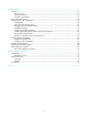
Contents Configuring Ethernet interfaces ··································································································································· 1 Overview············································································································································································ 1 Performing general configurations ························································································································
Types of MAC address entries ····························································································································· 31 Configuring static, dynamic, and destination blackhole MAC address entries ······················································ 31 Adding or modifying a static or dynamic MAC address entry in system view ·············································· 31 Adding or modifying a static or dynamic MAC address entry in interface view·······················
Configuring LLDP ························································································································································ 57 Overview········································································································································································· 57 Basic concepts ···············································································································································
Configuring Ethernet interfaces All configuration tasks in this chapter are independent and optional. You can perform these configuration tasks in any order. Overview Ethernet is the most widespread wired LAN technology due to its flexibility, simplicity, and easy implementation. The AC side of your device supports Layer 2 Ethernet interfaces, which are physical Ethernet interfaces operating at the data link layer to forward traffic within a subnet between hosts.
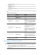
• Full-duplex mode (full)—Interfaces that operate in this mode can send and receive packets simultaneously. • Half-duplex mode (half)—Interfaces that operate in this mode cannot send and receive packets simultaneously. • Auto-negotiation mode (auto)—Interfaces that operate in this mode negotiate a duplex mode with their peers. You can set the speed of an Ethernet interface or enable it to automatically negotiate a speed with its peer. To configure an Ethernet interface: Step Command Remarks 1.
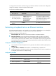
You might need to shut down and then bring up an Ethernet interface to activate some configuration changes, for example, the speed or duplex mode changes. To shut down an Ethernet interface: Step Enter system view. 1. Command Remarks system-view N/A • Enter Ethernet interface view: Enter Ethernet interface view or port group view. 2. interface interface-type interface-number • Enter port group view: port-group manual port-group-name Shut down the Ethernet interface. 3.
Configuring jumbo frame support An Ethernet interface might receive some frames larger than the standard Ethernet frame size (called "jumbo frames") during high-throughput data exchanges such as file transfers. Usually, an Ethernet interface discards jumbo frames. With jumbo frame support enabled, the interface can process frames larger than the standard Ethernet frame size yet within the specified range.
Configuring a Layer 2 Ethernet interface Configuring a port group Some interfaces on your device might use the same set of settings. To configure these interfaces in bulk rather than one by one, you can assign them to a port group. You create port groups manually. All settings made for a port group apply to all the member ports of the group.
Step 2. Enter Ethernet interface view or port group view. Command Remarks • Enter Ethernet interface view: To configure storm suppression on an Ethernet interface, enter Ethernet interface view. • Enter port group view: To configure storm suppression on a group of Ethernet interfaces, enter port group view. interface interface-type interface-number port-group manual port-group-name Optional. 3. Set the broadcast suppression threshold ratio.
Configuring loopback and null interfaces Configuring a loopback interface Introduction A loopback interface is a virtual interface. The physical layer state and link layer protocols of a loopback interface are always up unless the loopback interface is manually shut down. A loopback interface address can be configured as the source address of the IP packets that the device generates. Because loopback interface addresses are stable unicast addresses, they are usually used as device identifications.
Configuring the null interface Introduction A null interface is a completely software-based logical interface, and is always up. However, you cannot use it to forward data packets or configure an IP address or link layer protocol on it. With a null interface specified as the next hop of a static route to a specific network segment, any packets routed to the network segment are dropped. The null interface provides a simpler way to filter packets than ACL.
Task Display information about the null interface. Command display interface [ null ] [ brief [ down ] ] [ | { begin | exclude | include } regular-expression ] display interface null 0 [ brief ] [ | { begin | exclude | include } regular-expression ] Remarks Available in any view. Clear the statistics on a loopback interface. reset counters interface [ loopback [ interface-number ] ] Available in user view. Clear the statistics on the null interface.
Configuring VLANs Overview Ethernet is a shared-media network based on the CSMA/CD mechanism. A LAN built by using Ethernet is both a collision domain and a broadcast domain. In a LAN with plenty of hosts, the LAN might be full of collisions and broadcasts. As a result, the LAN performance is degraded or the LAN becomes unavailable. You can deploy bridges or Layer 2 switches in the LAN to reduce collisions, but this cannot confine broadcasts.
The format of VLAN-tagged frames is defined in IEEE 802.1Q issued in 1999. As shown in Figure 2, in a traditional Ethernet frame header, the field after the destination and source MAC addresses (DA & SA) is the Type field. This field indicates the upper layer protocol type. Figure 2 Traditional Ethernet frame format To identify VLAN information, IEEE 802.1Q inserts a four-byte VLAN tag between the DA & SA field and the Type field, as shown in Figure 3.
• IP subnet • Policy • Other criteria The device supports port-based VLAN and MAC-based VLAN. This chapter covers port-based VLAN and MAC-based VLAN. You can configure the two types of VLANs on a port at the same time. By default, the MAC-based VLAN has the priority over the port-based VLAN when the device assigns received packets to a VLAN. Protocols and standards IEEE 802.
Step Command Remarks Optional. 5. Configure a description for the VLAN. The default description is VLAN vlan-id, which is the ID of the VLAN. For example, the description of VLAN 100 is VLAN 0100 by default. description text Configuring basic settings of a VLAN interface You can use VLAN interfaces to provide Layer 3 communication between hosts of different VLANs. VLAN interfaces are virtual interfaces used for Layer 3 communication between different VLANs.
VLAN interface configuration example The configuration examples were created on the 11900/10500/7500 20G unified wired-WLAN module and might vary with device models. When configuring the 11900/10500/7500 20G unified wired-WLAN module, make sure the settings are correct (including VLAN settings) on the internal Ethernet interface that connects the module to the switch. For more information, see HP 11900/10500/7500 20G Unified Wired-WLAN Module Basic Configuration Guide.
[AC-WLAN-ESS2] quit [AC] vlan 10 [AC-vlan10] port WLAN-ESS 2 [AC-vlan10] quit # Create VLAN-interface 5, and configure its IP address as 192.168.0.10/24. [AC] interface vlan-interface 5 [AC-Vlan-interface5] ip address 192.168.0.10 24 [AC-Vlan-interface5] quit # Create VLAN-interface 10, and configure its IP address as 192.168.1.20/24. [AC] interface vlan-interface 10 [AC-Vlan-interface10] ip address 192.168.1.
[AC-Bridge-Aggregation1] port link-type trunk [AC-Bridge-Aggregation1] port trunk permit vlan 5 10 2. Configure the default gateway of Client 1 as 192.168.0.10. 3. Configure the default gateway of Client 2 as 192.168.1.20. Verifying the configuration # Verify that Client 1 and Client 2 can ping each other. (Details not shown.) # Display brief information about Layer 3 interfaces on the AC.
Figure 5 Network diagram VLAN 2 VLAN 2 VLAN 3 Device A Device B Device C Access links are required Trunk links are reuqired VLAN 3 Hybrid links are required PVID By default, VLAN 1 is the port VLAN ID (PVID) for all ports. You can configure the PVID for a port as required. When you configure the PVID on a port, use the following guidelines: • An access port can join only one VLAN. The VLAN to which the access port belongs is the PVID of the port.
Actions Access Trunk Hybrid • Receives the frame if Incoming tagged frame its VLAN ID is the same as the PVID. • Drops the frame if its VLAN ID is different from the PVID. • Receives the frame if its VLAN is permitted on the port. • Drops the frame if its VLAN is not permitted on the port. • Removes the tag and sends Outgoing frames Removes the VLAN tag and sends the frame. the frame if the frame carries the PVID tag and the port belongs to the PVID.
Step Command Remarks • The configuration made in WLAN-ESS • Enter Layer 2 Ethernet interface view: interface interface-type interface-number 2. Enter interface view or port group view. • Enter Layer 2 aggregate interface view: interface bridge-aggregation interface-number • Enter port group view: port-group manual port-group-name 3. 4. Configure the link type of the ports as access. port link-type access Assign the access ports to a VLAN.
Step 5. Command Configure the PVID of the trunk ports. Remarks port trunk pvid vlan vlan-id Optional. By default, the PVID is VLAN 1. To change the link type of a port from trunk to hybrid or from hybrid to trunk, you must set the link type to access first. After configuring the PVID for a trunk port, you must configure the trunk port to allow packets from the PVID to pass through. Assigning a hybrid port to a VLAN A hybrid port can carry multiple VLANs. You can assign it to a VLAN in interface view.
Port-based VLAN configuration example The configuration examples were created on the 11900/10500/7500 20G unified wired-WLAN module and might vary with device models. When configuring the 11900/10500/7500 20G unified wired-WLAN module, make sure the settings are correct (including VLAN settings) on the internal Ethernet interface that connects the module to the switch. For more information, see HP 11900/10500/7500 20G Unified Wired-WLAN Module Basic Configuration Guide.
[AC1-WLAN-ESS1] quit [AC1] vlan 100 [AC1-vlan100] port WLAN-ESS 1 [AC1-vlan100] quit # Create WLAN-ESS 2 and VLAN 200, and assign WLAN-ESS 2 to VLAN 200. [AC1] vlan 200 [AC1] interface WLAN-ESS 2 [AC1-WLAN-ESS2] quit [AC1-vlan200] port WLAN-ESS 2 [AC1-vlan200] quit # Create a clear-type WLAN service template 2, configure its SSID as vlan100, and bind WLAN-ESS 1 to the service template.
3. Configure Client 1 and Client 3 to be on the same IP subnet, for example, 192.168.100.0/24. 4. Configure Client 2 and Client 4 to be on the same IP subnet, for example, 192.168.200.0/24. Verifying the configuration # Verify that Client 1 and Client 3 can ping each other successfully, but they both fail to ping Client 2. (Details not shown.) # Verify that Client 2 and Client 4 can ping each other successfully, but they both fail to ping Client 1. (Details not shown.
2. Enable the MAC-based VLAN feature on the port. 3. Assign the port to MAC-based VLANs. With static MAC-based VLAN assignment configured on a port, the device processes received frames by using the following guidelines: • When the port receives an untagged frame, the device looks up the MAC address-to-VLAN map based on the source MAC address of the frame for a match. { { { { { The device first performs a fuzzy match.
• MAC-based VLANs are available only on hybrid ports. • The MAC-based VLAN feature is mainly configured on downlink ports of user access devices. Do not enable this function together with link aggregation. Configuration procedure To configure static MAC-based VLAN assignment: Step Command Remarks 1. Enter system view. system-view N/A 2. Associate a specific MAC address with a VLAN.
Step 6. Configure 802.1X, MAC, portal authentication, or any combination. Command Remarks For more information, see Security Command Reference. N/A MAC-based VLAN configuration example The configuration examples were created on the 11900/10500/7500 20G unified wired-WLAN module and might vary with device models.
Figure 7 Network diagram Configuration considerations To meet the network requirements, you must perform the following tasks: • Create VLANs 100 and 200. • Configure the uplink ports of AC 1 and AC 2 as trunk ports, and assign them to VLANs 100 and 200. • Configure the downlink ports of Device as trunk ports, and assign them to VLANs 100 and 200. Assign the uplink ports of Device to VLANs 100 and 200.
# Associate the MAC address of Client 1 with VLAN 100, and the MAC address of Client 2 with VLAN 200. [AC1] mac-vlan mac-address 000d-88f8-4e71 vlan 100 [AC1] mac-vlan mac-address 0014-222c-aa69 vlan 200 # Configure Client 1 and Client 2 to access the network through WLAN-ESS 1. [AC1] interface wlan-ess 1 # Configure WLAN-ESS 1 as a hybrid port to send packets from VLANs 100 and 200 untagged. [AC1-WLAN-ESS1] port link-type hybrid [AC1-WLAN-ESS1] port hybrid vlan 100 200 untagged Please wait... Done.
[Device-Ethernet1/3] port link-type trunk [Device-Ethernet1/3] port trunk permit vlan 100 200 [Device-Ethernet1/3] quit [Device] interface ethernet 1/4 [Device-Ethernet1/4] port link-type trunk [Device-Ethernet1/4] port trunk permit vlan 100 200 [Device-Ethernet1/4] quit 3. Configure AC 2 in the same way AC 1 is configured. (Details not shown.) Verifying the configuration # Verify that Client 1 can access Server 1 only, and Client 2 can access Server 2 only. (Details not shown.
Configuring the MAC address table This document covers only the configuration of unicast MAC address entries, including static, dynamic, and destination blackhole MAC address entries. The MAC address table configuration tasks can be performed in any order. Overview To reduce single-destination packet flooding in a switched LAN, an Ethernet device uses a MAC address table for forwarding frames. This table describes from which interface a MAC address (or host) can be reached.
Manually configuring MAC address entries With dynamic MAC address learning, a device does not distinguish between illegitimate and legitimate frames. For example, when a hacker sends frames with a forged source MAC address to an interface different from the one with which the real MAC address is associated, the device performs the following tasks: 1. Creates an entry for the forged MAC address. 2. Forwards frames destined for the legal user to the hacker instead.
Adding or modifying a static or dynamic MAC address entry in interface view Step Command Remarks 1. Enter system view. system-view N/A 2. Enter Layer 2 Ethernet or aggregate interface view. interface interface-type interface-number N/A 3. Add or modify a static or dynamic MAC address entry. By default, no MAC address entry is configured. mac-address { dynamic | static } mac-address vlan vlan-id Make sure you have created the VLAN and assigned the interface to the VLAN.
To disable MAC address learning on an interface or a port group: Step Command Remarks N/A 1. Enter system view. system-view 2. Enable global MAC address learning. undo mac-address mac-learning disable Optional. By default, global MAC address learning is enabled. Use either command. • Enter Layer 2 Ethernet or Enter interface view or port group view. 3.
Step 2. Command Remarks Optional. Configure the aging timer for dynamic MAC address entries. mac-address timer { aging seconds | no-aging } By default, the aging timer is 300 seconds. The no-aging keyword disables the aging timer. Configuring the MAC learning limit on interfaces To prevent a large MAC address table from degrading forwarding performance, limit the number of MAC addresses that an interface can learn.
Task Command Remarks Display MAC address statistics. display mac-address statistics [ | { begin | exclude | include } regular-expression ] Available in any view. MAC address table configuration example The configuration example was created on the 11900/10500/7500 20G unified wired-WLAN module and might vary with device models.
Figure 8 Network diagram Configuration procedure # Add a static MAC address entry. system-view [AC] mac-address static 000f-e235-dc71 interface Ten-GigabitEthernet 1/0/1 vlan 1 # Add a destination blackhole MAC address entry. [AC] mac-address blackhole 000f-e235-abcd vlan 1 # Set the aging timer for dynamic MAC address entries to 500 seconds. [AC] mac-address timer aging 500 Verifying the configuration # Display MAC address entries on Ten-GigabitEthernet 1/0/1.
Configuring Ethernet link aggregation Overview Ethernet link aggregation, or simply link aggregation, combines multiple physical Ethernet ports into one logical link called an "aggregate link." Link aggregation delivers the following benefits: • Increases bandwidth beyond the limits of any single link. In an aggregate link, traffic is distributed across the member ports. • Improves link reliability. The member ports back up one another dynamically.
Aggregation states of member ports in an aggregation group A member port in an aggregation group can be in either of the following aggregation states: • Selected—A Selected port can forward user traffic. • Unselected—An Unselected port cannot forward user traffic. When a Selected port fails, an Unselected port might become a Selected port and forward user traffic.
Link aggregation modes Link aggregation can be done in dynamic mode or static mode. Dynamic link aggregation uses the IEEE 802.3ad LACP, but static link aggregation does not. Table 2 compares the two aggregation modes. Table 2 A comparison between static and dynamic aggregation modes Aggregation mode Static Dynamic LACP status on member ports Pros Cons Disabled Aggregation is stable. Peers do not affect the aggregation state of member ports.
LACP timeout interval specifies how long a member port waits to receive LACPDUs from the peer port. If a local member port fails to receive LACPDUs from the peer within three times the LACP timeout interval, the member port assumes that the peer port has failed. You can configure the LACP timeout interval as either the short timeout interval (1 second) or the long timeout interval (30 seconds). Aggregating links in static mode LACP is disabled on the member ports in a static aggregation group.
Figure 10 Setting the aggregation state of a member port in a static aggregation group Set the aggregation state of a member port Yes Is there any hardware restriction? No No Is the port up? Yes Port attribute/class 2 configurations same as the reference port? No Yes More candidate ports than max.
2. The system with the smaller system ID chooses the port with the smallest port ID as the reference port. (A port ID contains a port aggregation priority and a port number.) The port with the lower aggregation priority value is chosen. If two ports have the same aggregation priority, the system compares their port numbers. The port with the smaller port number becomes the reference port.
• To ensure stable aggregation and service continuity, do not change the port attribute configurations or class-two configurations on any member port. • When the aggregation state of a local port changes, the aggregation state of its peer port also changes. • After the Selected port limit has been reached, a port joining the aggregation group is put in Selected state if it is more eligible than a current member port.
Step Command Remarks 2. Create a Layer 2 aggregate interface and enter Layer 2 aggregate interface view. interface bridge-aggregation interface-number When you create a Layer 2 aggregate interface, the system automatically creates a Layer 2 static aggregation group numbered the same. 3. Exit to system view. quit N/A 4. Assign a Layer 2 Ethernet interface to the aggregation group. a. interface interface-type interface-number b.
Step 5. 6. Exit to system view. Assign a Layer 2 Ethernet interface to the aggregation group. Command Remarks quit N/A a. Enter Layer 2 Ethernet interface view: interface interface-type interface-number Repeat these two sub-steps to assign more Layer 2 Ethernet interfaces to the aggregation group. b. Assign the interface to the specified Layer 2 aggregation group: port link-aggregation group number Optional. By default, the aggregation priority of a port is 32768. 7.
Step Command Remarks Optional. Configure the description of the aggregate interface. 3. By default, the description of an interface is in the format of interface-name Interface, such as Bridge-Aggregation1 Interface. description text Enabling link state traps for an aggregate interface You can configure an aggregate interface to generate linkUp trap messages when its link goes up and linkDown trap messages when its link goes down.
Restoring the default settings for an aggregate interface Step Command 1. Enter system view. system-view 2. Enter Layer 2 aggregate interface view. interface bridge-aggregation interface-number 3. Restore the default settings for the aggregate interface. default Configuring load sharing for link aggregation groups You can determine how traffic is load-shared in a link aggregation group by configuring load sharing criteria.
Displaying and maintaining Ethernet link aggregation Task Display information about Layer 2 aggregate interfaces. Command display interface [ bridge-aggregation ] [ brief [ down ] ] [ | { begin | exclude | include } regular-expression ] display interface bridge-aggregation interface-number [ brief ] [ | { begin | exclude | include } regular-expression ] Remarks Available in any view. Display the local system ID.
Configuring Layer 2 forwarding Layer 2 forwarding includes the following categories: • Normal • Fast Configuring normal Layer 2 forwarding If the destination MAC address of an incoming packet matches the MAC address of the receiving Layer 3 interface, the device forwards the packet through that interface. If not, the device performs normal Layer 2 forwarding through a Layer 2 interface.
Step Command Remarks N/A 1. Enter system view. system-view 2. Enable fast Layer 2 forwarding. mac-fast-forwarding Optional. Enabled by default. Displaying and maintaining fast Layer 2 forwarding Task Command Remarks Display fast Layer 2 forwarding information. display mac-fast-forwarding cache { all | { destination-mac mac-address | source-mac mac-address | vlan vlan-id }* } [ verbose ] [ | { begin | exclude | include } regular-expression ] Available in any view.
Configuring PPPoE server Support for this feature depends on the device model. For more information, see About the Configuration Guides for HP Unified Wired-WLAN Products. Overview Point-to-Point Protocol over Ethernet (PPPoE) extends PPP by transporting PPP packets encapsulated in Ethernet over point-to-point links. PPPoE can provide access to the Internet for the hosts in an Ethernet through a remote access device and implement access control and accounting on a per-host basis.
Figure 13 Network structure 2 PPPoE client Host A PPPoE server Internet PPPoE client Router Host B Protocols and standards RFC 2516, A Method for Transmitting PPP Over Ethernet (PPPoE) Configuring a PPPoE server Step Command Remarks 1. Enter system view. system-view N/A 2. Create a virtual template (VT) interface. interface virtual-template number This operation also leads you to VT interface view. 3. Enter VLAN interface view. interface interface-type interface-number N/A 4.
Step Command Remarks Optional. 10. Set the upper threshold for the PPPoE abnormal offline event percentage. pppoe-server abnormal-offline-percent threshold number 100 by default. If the PPPoE abnormal offline event percentage in the last 5 minutes exceeds this threshold, the system outputs a trap message. Optional. 11. Set the lower threshold for the PPPoE normal offline event percentage. pppoe-server normal-offline-percent threshold number 12. Configure authentication and accounting on PPP users.
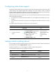
Network requirements As shown in Figure 14, the AC connects to the Internet through VLAN-interface 2. The wireless clients support the PPPoE client. Configure the PPPoE server on the AC to perform the following functions: • Performs local authentication and assigns IP addresses for the clients. • Uses VLAN-interface 1 to provide Internet access for the clients.
# Add a PPPoE user. system-view [AC] local-user user1 [AC-luser-user1] password simple pass1 [AC-luser-user1] service-type ppp [AC-luser-user1] quit # Configure virtual-template 1 on the AC. [AC] interface virtual-template 1 [AC-Virtual-Template1] ppp authentication-mode ms-chap domain system [AC-Virtual-Template1] remote address pool 1 [AC-Virtual-Template1] ip address 1.1.1.1 255.0.0.0 [AC-Virtual-Template1] quit # Configure the PPPoE server on the AC.
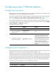
Configuring FPGA fast forwarding Support for this feature depends on the device model. For more information, see About the Configuration Guides for HP Unified Wired-WLAN Products. Overview FPGA fast forwarding greatly improves an AC's forwarding efficiency by performing hardware forwarding with an FPGA card, which forwards wireless packets according to fast forwarding entries. Wireless packets of the following categories are forwarded by software: • Packets matching no fast forwarding entries.
Configuring LLDP Overview In a heterogeneous network, a standard configuration exchange platform makes sure different types of network devices from different vendors can discover one another and exchange configuration. IETF drafted the Link Layer Discovery Protocol (LLDP) in IEEE 802.1AB. The protocol operates on the data link layer to exchange device information between directly connected devices.
Field Description FCS Frame check sequence, a 32-bit CRC value used to determine the validity of the received Ethernet frame. LLDP frame encapsulated in SNAP • Figure 16 SNAP-encapsulated LLDP frame Table 5 Fields in a SNAP-encapsulated LLDP frame Field Description Destination MAC address MAC address to which the LLDP frame is advertised. It is fixed at 0x0180-C200-000E, a multicast MAC address. Source MAC address MAC address of the sending port. Type SNAP type for the upper layer protocol.
• Basic management TLVs • Organizationally (IEEE 802.1 and IEEE 802.3) specific TLVs • LLDP-MED (media endpoint discovery) TLVs Basic management TLVs are essential to device management. Organizationally specific TLVs and LLDP-MED TLVs are used for enhanced device management, and they are defined by standardization or other organizations and are optional for LLDPDUs. • Basic management TLVs: Table 6 lists the basic management TLV types. Some of them are mandatory for LLDPDUs.
NOTE: H3C devices support only receiving protocol identity TLVs. • IEEE 802.3 organizationally specific TLVs Table 8 IEEE 802.3 organizationally specific TLVs Type Description MAC/PHY Configuration/Status Contains the bit-rate and duplex capabilities of the sending port, support for auto negotiation, enabling status of auto negotiation, and the current rate and duplex mode. Contains the power supply capabilities of the port: Power Via MDI • • • • • Port class (PSE or PD). Power supply mode.
Type Description Software Revision Allows a terminal device to advertise its software version. Serial Number Allows a terminal device to advertise its serial number. Manufacturer Name Allows a terminal device to advertise its vendor name. Model Name Allows a terminal device to advertise its model name. Asset ID Allows a terminal device to advertise its asset ID. The typical case is that the user specifies the asset ID for the endpoint to assist directory management and asset tracking.
Receiving LLDP frames An LLDP-enabled port that is operating in TxRx mode or Rx mode examines the validity of TLVs carried in every received LLDP frame. If valid, the information is saved and an aging timer is set for it based on the TTL value in the Time to Live TLV carried in the LLDP frame. If the TTL value is zero, the information ages out immediately. Protocols and standards • IEEE 802.
Step 2. Enable LLDP globally. 3. Enter Ethernet interface view or port group view. Command Remarks lldp global enable By default, LLDP is disabled globally. • Enter Layer 2 Ethernet interface view: interface interface-type interface-number • Enter port group view: Use either command. port-group manual port-group-name Optional. 4. Enable LLDP. lldp enable By default, LLDP is enabled on a port. Setting the LLDP operating mode Step 1. Enter system view. 2.
Step 1. Enter system view. 2. Enter Ethernet interface view or port group view. Command Remarks system-view N/A • Enter Layer 2 Ethernet interface view: interface interface-type interface-number • Enter port group view: Use either command. port-group manual port-group-name 3. Enable LLDP polling and set the polling interval. By default, LLDP polling is disabled. lldp check-change-interval interval Configuring the advertisable TLVs Step 1. Enter system view. 2.
Step Command Remarks • Enter Layer 2 Ethernet Enter Ethernet interface view or port group view. 2. interface view: interface interface-type interface-number • Enter port group view: Use either command. port-group manual port-group-name Optional. 3. 4. By default, the management address is sent through LLDPDUs. Allow LLDP to advertise the management address in LLDPDUs and configure the advertised management address.
Step Command 2. Set the TTL multiplier. lldp hold-multiplier value 3. Set the LLDP frame transmission interval. lldp timer tx-interval interval 4. Set the LLDP frame transmission delay. lldp timer tx-delay delay Set the number of LLDP frames sent each time fast LLDP frame transmission is triggered. lldp fast-count count 5. Remarks Optional. The default setting is 4. Optional. The default setting is 30 seconds. Optional. The default setting is 2 seconds. Optional. The default setting is 3.
With CDP compatibility enabled, your device can receive and recognize CDP packets from a Cisco IP phone and respond with CDP packets, which carry TLVs with the voice VLAN configuration. The IP phone automatically configures the voice VLAN according to TLVs with the voice VLAN configuration. As a result, voice traffic is confined in the configured voice VLAN, and differentiated from other types of traffic. For more information about voice VLANs, see "Configuring voice VLANs.
Configuring LLDP trapping LLDP trapping notifies the NMS of events such as newly-detected neighboring devices and link failures. To prevent excessive LLDP traps from being sent when the topology is unstable, set a trap transmission interval for LLDP. To configure LLDP trapping: Step 1. Enter system view. 2. Enter Ethernet interface view or port group view.
LLDP configuration examples The configuration examples were created on the 11900/10500/7500 20G unified wired-WLAN module and might vary with device models. When configuring the 11900/10500/7500 20G unified wired-WLAN module, make sure the settings are correct (including VLAN settings) on the internal Ethernet interface that connects the module to the switch. For more information, see HP 11900/10500/7500 20G Unified Wired-WLAN Module Basic Configuration Guide.
[AC-GigabitEthernet1/0/1] quit # Enable LLDP on GigabitEthernet 1/0/2. By default, LLDP is enabled on ports. [AC] interface GigabitEthernet1/0/2 [AC-GigabitEthernet1/0/2] lldp enable # Set the LLDP operating mode to Rx on GigabitEthernet 1/0/2. [AC-GigabitEthernet1/0/2] lldp admin-status rx [AC-GigabitEthernet1/0/2] quit 2. Configure the switch: # Enable LLDP globally. system-view [Switch] lldp enable # Enable LLDP on GigabitEthernet 1/0/1. By default, LLDP is enabled on ports.
Port 3 [GigabitEthernet1/0/2]: Port status of LLDP : Enable Admin status : Rx_Only Trap flag : No Polling interval : 0s Number of neighbors: 1 Number of MED neighbors : 0 Number of CDP neighbors : 0 Number of sent optional TLV : 23 Number of received unknown TLV : 0 Port 4 [GigabitEthernet1/0/3]: Port status of LLDP : Enable Admin status : Tx_Rx Trap flag : No Polling interval : 0s Number of neighbors: 0 Number of MED neighbors : 0 Number of CDP neighbors : 0 Number of sent op
Port 7 [GigabitEthernet1/0/6]: Port status of LLDP : Enable Admin status : Tx_Rx Trap flag : No Polling interval : 0s Number of neighbors: 0 Number of MED neighbors : 0 Number of CDP neighbors : 0 Number of sent optional TLV : 23 Number of received unknown TLV : 0 Port 8 [GigabitEthernet1/0/7]: Port status of LLDP : Enable Admin status : Tx_Rx Trap flag : No Polling interval : 0s Number of neighbors: 0 Number of MED neighbors : 0 Number of CDP neighbors : 0 Number of sent opti
# Remove the link between the AC and the switch. (Details not shown.) # Verify that GigabitEthernet 1/0/2 of the AC does not connect to any neighboring devices.
Number of sent optional TLV : 23 Number of received unknown TLV : 0 Port 5 [GigabitEthernet1/0/4]: Port status of LLDP : Enable Admin status : Tx_Rx Trap flag : No Polling interval : 0s Number of neighbors: 0 Number of MED neighbors : 0 Number of CDP neighbors : 0 Number of sent optional TLV : 23 Number of received unknown TLV : 0 Port 6 [GigabitEthernet1/0/5]: Port status of LLDP : Enable Admin status : Tx_Rx Trap flag : No Polling interval : 0s Number of neighbors: 0 Number of
Number of sent optional TLV : 23 Number of received unknown TLV : 0 Port 10 [Ten-GigabitEthernet1/0/9]: Port status of LLDP : Enable Admin status : Tx_Rx Trap flag : No Polling interval : 0s Number of neighbors: 0 Number of MED neighbors : 0 Number of CDP neighbors : 0 Number of sent optional TLV : 23 Number of received unknown TLV : 0 Port 11 [Ten-GigabitEthernet1/0/10]: Port status of LLDP : Enable Admin status : Tx_Rx Trap flag : No Polling interval : 0s Number of neighbors: 0
Support and other resources Contacting HP For worldwide technical support information, see the HP support website: http://www.hp.
Conventions This section describes the conventions used in this documentation set. Command conventions Convention Description Boldface Bold text represents commands and keywords that you enter literally as shown. Italic Italic text represents arguments that you replace with actual values. [] Square brackets enclose syntax choices (keywords or arguments) that are optional. { x | y | ... } Braces enclose a set of required syntax choices separated by vertical bars, from which you select one.
Network topology icons Represents a generic network device, such as a router, switch, or firewall. Represents a routing-capable device, such as a router or Layer 3 switch. Represents a generic switch, such as a Layer 2 or Layer 3 switch, or a router that supports Layer 2 forwarding and other Layer 2 features. Represents an access controller, a unified wired-WLAN module, or the switching engine on a unified wired-WLAN switch. Represents an access point.
Index CDELMOPR Displaying and maintaining LLDP,68 C Displaying and maintaining loopback and null interfaces,8 Configuration procedure,56 Configuring a Layer 2 aggregation group,43 Displaying and maintaining MAC address tables,34 Configuring a Layer 2 Ethernet interface,5 Displaying and maintaining PPPoE,53 Configuring a loopback interface,7 Displaying and maintaining VLANs,29 Configuring a PPPoE server,52 E Configuring an aggregate interface,45 Configuring basic settings of a VLAN interface,13 E