HP Unified Wired-WLAN Products Layer 3 Configuration Guide HP 830 Unified Wired-WLAN PoE+ Switch Series HP 850 Unified Wired-WLAN Appliance HP 870 Unified Wired-WLAN Appliance HP 11900/10500/7500 20G Unified Wired-WLAN Module Part number: 5998-4791 Software version: 3507P22 (HP 830 PoE+ Switch Series) 2607P22 (HP 850 Appliance) 2607P22 (HP 870 Appliance) 2507P22 (HP 11900/10500/7500 20G Module) Document version: 6W101-20140418
Legal and notice information © Copyright 2014 Hewlett-Packard Development Company, L.P. No part of this documentation may be reproduced or transmitted in any form or by any means without prior written consent of Hewlett-Packard Development Company, L.P. The information contained herein is subject to change without notice.
Contents Configuring ARP ··························································································································································· 1 Overview············································································································································································ 1 ARP message format ·······························································································································
DHCP message format··················································································································································· 20 DHCP options ································································································································································· 21 Common DHCP options ········································································································································ 21 Cust
DHCP relay agent support for Option 82 ·········································································································· 47 DHCP relay agent configuration task list ····················································································································· 47 Enabling DHCP ······························································································································································ 48 Enabling the DHCP relay a
DHCPv6 overview ······················································································································································ 74 Basic concepts ································································································································································ 74 DHCPv6 address/prefix assignment ···························································································································· 75 Ra
Configuring DHCPv6 snooping ····························································································································· 111 Overview······································································································································································· 111 Enabling DHCPv6 snooping ······································································································································· 112 Configuri
Configuring static NAT ······································································································································· 145 Configuring dynamic NAT ································································································································· 146 Configuring an internal server ···································································································································· 147 Configuring DNS mapping
Enabling sending ICMPv6 redirect messages ·································································································· 177 Displaying and maintaining IPv6 basics configuration···························································································· 177 IPv6 basics configuration example ···························································································································· 178 Troubleshooting IPv6 basics configuration ·············
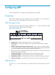
Configuring ARP This chapter describes how to configure the Address Resolution Protocol (ARP). Overview ARP resolves IP addresses into physical addresses such as MAC addresses. On an Ethernet LAN, a device uses ARP to get the MAC address of the target device for a packet. ARP message format ARP uses two types of messages, ARP request and ARP reply. Figure 1 shows the format of the ARP request/reply. Numbers in the figure refer to field lengths.
1. Host A looks through its ARP table for an ARP entry for Host B. If an entry is found, Host A uses the MAC address in the entry to encapsulate the IP packet into a data link layer frame and sends the frame to Host B. 2. If Host A finds no entry for Host B, Host A buffers the packet and broadcasts an ARP request.
Dynamic ARP entry ARP automatically creates and updates dynamic entries. A dynamic ARP entry is removed when its aging timer expires or the output interface goes down, and it can be overwritten by a static ARP entry. Static ARP entry A static ARP entry is manually configured and maintained. It does not age out, and cannot be overwritten by a dynamic ARP entry. Static ARP entries protect communication between devices, because attack packets cannot modify the IP-to-MAC mapping in a static ARP entry.
Configuring the maximum number of dynamic ARP entries for an interface An interface can dynamically learn ARP entries. , To prevent an interface from holding too many ARP entries, you can set the maximum number of dynamic ARP entries that the interface can learn. When the maximum number is reached, the interface stops learning ARP entries. A Layer 2 interface can learn an ARP entry only when both its maximum number and the VLAN interface's maximum number are not reached.
When dynamic ARP entry check is enabled, the device cannot learn dynamic ARP entries containing multicast MAC addresses. When dynamic ARP entry check is disabled, the device can learn dynamic ARP entries containing multicast MAC addresses. To enable dynamic ARP entry check: Step Command Remarks N/A 1. Enter system view. system-view 2. Enable dynamic ARP entry check. arp check enable Optional. Enabled by default.
Task Command Remarks Display the aging timer of dynamic ARP entries. display arp timer aging [ | { begin | exclude | include } regular-expression ] Available in any view. Clear ARP entries from the ARP table. reset arp { all | dynamic | static | interface interface-type interface-number } Available in user view. ARP configuration example The configuration examples were created on the 11900/10500/7500 20G unified wired-WLAN module and might vary by device model.
Configuring gratuitous ARP Overview In a gratuitous ARP packet, the sender IP address and the target IP address are the IP address of the sending device. A device sends a gratuitous ARP packet for either of the following purposes: • Determine whether its IP address is already used by another device. If the IP address is already used, the device is informed of the conflict by an ARP reply. • Inform other devices of a change of its MAC address.
The master router of a VRRP group can periodically send gratuitous ARP packets to the hosts on the local network, so that the hosts can update local ARP entries and avoid using the virtual IP address of the VRRP group. If the virtual IP address of the VRRP group is associated with a virtual MAC address, the sender MAC address in the gratuitous ARP packet is the virtual MAC address of the virtual router.
Configuring ARP snooping Overview ARP snooping is used in Layer 2 switching networks. It creates ARP snooping entries by using information in ARP packets. The ARP snooping entries can be used by ARP fast-reply. If ARP snooping is enabled, all ARP packets received by the interfaces are redirected to the CPU. The CPU uses the sender IP and MAC addresses of the ARP packets, and receiving VLAN and port to create ARP snooping entries.
Configuring ARP fast-reply Overview In a wireless network, APs are connected to an AC through tunnels, so that clients can communicate with the AC through APs and can further access the gateway through the AC. If a client broadcasts an ARP request through the associated AP, the AC needs to send the ARP request to all the other APs, wasting tunnel resources and affecting forwarding performance. The ARP fast-reply mechanism can solve this problem.
ARP fast-reply configuration example The configuration examples were created on the 11900/10500/7500 20G unified wired-WLAN module and might vary by device model. When configuring the 11900/10500/7500 20G unified wired-WLAN module, make sure the settings are correct (including VLAN settings) on the internal Ethernet interface that connects the module to the switch. For more information, see HP 11900/10500/7500 20G Unified Wired-WLAN Module Basic Configuration Guide.
# Enable WLAN, which is enabled by default. system-view [AC] wlan enable # Create a WLAN-ESS interface. [AC] interface wlan-ess 1 [AC-WLAN-ESS1] quit # Define a WLAN service template and bind the WLAN-ESS interface to this service template. [AC] wlan service-template 1 clear [AC-wlan-st-1] ssid abc [AC-wlan-st-1] bind wlan-ess 1 [AC-wlan-st-1] authentication-method open-system [AC-wlan-st-1] service-template enable [AC-wlan-st-1] quit # Configure AP 1 on the AC.
Configuring IP addressing This chapter describes IP addressing basic and manual IP address assignment for interfaces. Dynamic IP address assignment (BOOTP and DHCP) and PPP address negotiation are beyond the scope of this chapter. Overview This section describes the IP addressing basics. IP addressing uses a 32-bit address to identify each host on a network. To make addresses easier to read, they are written in dotted decimal notation, each address being four octets in length.
Class Address range Remarks C 192.0.0.0 to 223.255.255.255 N/A D 224.0.0.0 to 239.255.255.255 Multicast addresses. E 240.0.0.0 to 255.255.255.255 Reserved for future use except for the broadcast address 255.255.255.255. Special IP addresses The following IP addresses are for special use and cannot be used as host IP addresses. • IP address with an all-zero net ID—Identifies a host on the local network. For example, IP address 0.0.0.
With subnetting—Using the first 9 bits of the host-id for subnetting provides 512 (29) subnets. However, only 7 bits remain available for the host ID. This allows 126 (27 – 2) hosts in each subnet, a total of 64512 hosts (512 × 126). • Assigning an IP address to an interface You can assign an interface one primary address and multiple secondary addresses. Generally, you only need to assign the primary address to an interface. In some cases, you must assign secondary IP addresses to the interface.
Task Command Remarks Display brief IP configuration information about a Layer 3 interface or all Layer 3 interfaces. display ip interface [ interface-type [ interface-number ] ] brief [ | { begin | exclude | include } regular-expression ] Available in any view. IP addressing configuration example The configuration examples were created on the 11900/10500/7500 20G unified wired-WLAN module and might vary by device models.
Configuration procedure # Assign a primary IP address and a secondary IP address to VLAN-interface 1. system-view [AC] interface vlan-interface 1 [AC-Vlan-interface1] ip address 172.16.1.1 255.255.255.0 [AC-Vlan-interface1] ip address 172.16.2.1 255.255.255.0 sub # Set the gateway address to 172.16.1.1 on the PCs attached to the subnet 172.16.1.0/24, and to 172.16.2.1 on the PCs attached to the subnet 172.16.2.0/24.
DHCP overview The Dynamic Host Configuration Protocol (DHCP) provides a framework to assign configuration information to network devices. As shown in Figure 7, a DHCP client can obtain an IP address and other configuration parameters from a DHCP server on another subnet through a DHCP relay agent. For more information about the DHCP relay agent, see "Configuring the DHCP relay agent.
Dynamic IP address allocation process Figure 8 Dynamic IP address allocation process 1. The client broadcasts a DHCP-DISCOVER message to locate a DHCP server. 2. Each DHCP server offers configuration parameters such as an IP address to the client in a DHCP-OFFER message. The sending mode of the DHCP-OFFER is determined by the flag field in the DHCP-DISCOVER message. For related information, see "DHCP message format." 3.
DHCP message format Figure 9 shows the DHCP message format, which is based on the BOOTP message format although DHCP uses some of the fields in significantly different ways. The numbers in parentheses indicate the size of each field in bytes. Figure 9 DHCP message format • op—Message type defined in option field. 1 = REQUEST, 2 = REPLY • htype, hlen—Hardware address type and length of the DHCP client. • hops—Number of relay agents a request message traveled.
DHCP options DHCP uses the same message format as BOOTP, but DHCP uses the Option field to carry information about dynamic address allocation and to provide additional configuration information to clients. Figure 10 DHCP option format Common DHCP options The following are common DHCP options: • Option 3—Router option. It specifies the gateway address. • Option 6—DNS server option. It specifies the DNS server's IP address. • Option 33—Static route option.
Vendor-specific option (Option 43) DHCP servers and clients use Option 43 to exchange vendor-specific configuration information. In the HP implementation of Option 43, the discovery sequence for the APP is unicast -> broadcast -> dns. For Bootware, the sequence is: broadcast -> unicast -> dns. An AP, acting as a DHCP client, can obtain the AC address through Option 43 and use the AC address to obtain the boot file or other control information from the AC.
• Normal padding format: { Sub-option 1—Contains the VLAN ID and interface number of the interface that received the client's request. The value of the sub-option type is 1, and that of the circuit ID type is 0. Figure 13 Sub-option 1 in normal padding format { Sub-option 2—Contains the MAC address of the DHCP relay agent interface or the MAC address of the DHCP snooping device that received the client's request. The value of the sub-option type is 2, and that of the remote ID type is 0.
• Sub-option 4—Specifies the failover route that includes the IP address and the number of the target user. A Session Initiation Protocol (SIP) user uses this IP address and number to directly establish a connection to the target SIP user when both the primary and backup calling processors are unreachable. For Option 184, you must define sub-option 1 to make other sub-options take effect.
Configuring the DHCP server Overview The DHCP server is well suited to networks where: • Manual configuration and centralized management are difficult to implement. • IP addresses are limited. For example, an ISP limits the number of concurrent online users, and most users must acquire IP addresses dynamically. • Most hosts do not need fixed IP addresses.
2. If the receiving interface has an extended address pool referenced, the DHCP server assigns an IP address from this address pool. If no IP address is available in the address pool, the DHCP server fails to assign an address to the client. For the configuration of such an address pool, see "Configuring dynamic address allocation for an extended address pool." 3.
Task Remarks Configuring the DHCP server security functions Optional. Enabling client offline detection Optional. Enabling handling of Option 82 Optional. Specifying the threshold for sending trap messages Optional. Configuring an address pool on the DHCP server Configuration task list Task Remarks Creating a DHCP address pool Required.
A common address pool and an extended address pool are different in address allocation mode configuration. Configurations of other parameters (such as the domain name suffix and DNS server address) for them are the same. Configuring address allocation mode for a common address pool CAUTION: You can configure either a static binding or dynamic address allocation for a common address pool, but not both. You need to specify a subnet for dynamic address allocation.
Step Command Remarks • Specify the MAC address: Specify the MAC address or client ID. 4. static-bind mac-address mac-address Use either of the commands. • Specify the client ID: Neither is bound statically by default. expired { day day [ hour hour [ minute minute [ second second ] ] ] | unlimited } Optional. static-bind client-identifier client-identifier Specify the lease duration for the IP address. 5. By default, the lease duration of the IP address is unlimited.
Configuring dynamic address allocation for an extended address pool Extended address pools support dynamic address allocation only. When configuring an extended address pool, you must specify: • Assignable IP address range • Mask After the assignable IP address range and the mask are specified, the address pool becomes valid. To configure dynamic address allocation for an extended address pool: Step Command Remarks 1. Enter system view. system-view N/A 2. Enter extended address pool view.
Step Specify a domain name suffix. 3. Command Remarks domain-name domain-name Not specified by default. Configuring DNS servers for the client To access hosts on the Internet through domain names, a DHCP client must contact a DNS server to resolve names. You can specify up to eight DNS servers in a DHCP address pool. To configure DNS servers in a DHCP address pool: Step Command Remarks 1. Enter system view. system-view N/A 2. Enter DHCP address pool view.
Configuring BIMS server information for the client Perform this task to provide the Branch Intelligent Management System (BIMS) server IP address, port number, and shared key for the clients. The DHCP clients contact the BIMS server to get configuration files and perform software update and backup. To configure the BIMS server IP address, port number, and shared key in the DHCP address pool: Step Command Remarks 1. Enter system view. system-view N/A 2. Enter DHCP address pool view.
Step Command Remarks Optional. 5. Configure the voice VLAN. voice-config voice-vlan vlan-id { disable | enable } 6. Specify the failover IP address and dialer string. voice-config fail-over ip-address dialer-string No voice VLAN is configured by default. Optional. No failover IP address or dialer string is specified by default. Other configurations take effect only after you specify an IP address for the network calling processor.
Step Command Remarks 1. Enter system view. system-view N/A 2. Enter DHCP address pool view. dhcp server ip-pool pool-name [ extended ] N/A 3. Specify the IP address of a server. next-server ip-address Not specified by default. Configuring self-defined DHCP options CAUTION: Be careful when configuring self-defined DHCP options because such configuration may affect DHCP operation. By configuring self-defined DHCP options, you can • Define new DHCP options.
Option Option name Corresponding command Command parameter 66 TFTP server name tftp-server ascii 67 Bootfile name bootfile-name ascii 43 Vendor Specific Information N/A hex Enabling DHCP Enable DHCP to validate other DHCP configurations. To enable DHCP: Step Command Remarks 1. Enter system view. system-view N/A 2. Enable DHCP. dhcp enable The default setting is disabled by default. 3. Enable the DHCP server to output logs. dhcp server log enable Optional.
Configuration procedure To enable the DHCP server on an interface: Step Command Remarks 1. Enter system view. system-view N/A 2. Enter interface view. interface interface-type interface-number N/A 3. Enable the DHCP server on the interface. dhcp select server global-pool [ subaddress ] Optional. The default setting is enabled by default.
Enabling unauthorized DHCP server detection Unauthorized DHCP servers on a network may assign wrong IP addresses to DHCP clients. With unauthorized DHCP server detection enabled, the DHCP server checks whether a DHCP request contains Option 54 (Server Identifier Option). If yes, the DHCP server records in the option the IP address of the DHCP server that assigned an IP address to a requesting DHCP client and records the receiving interface.
Enable authorized ARP—The ARP automatic learning function is disabled after you enable authorized ARP. ARP entries are added according to the IP address leases specified by the DHCP server, to avoid learning incorrect ARP entries. • The DHCP server works with authorized ARP for the following purposes: • Only the clients that have obtained IP addresses from the DHCP server and have their ARP entries recorded on the DHCP server are authorized clients and can access the network normally.
Step Command Remarks 1. Enter system view. system-view N/A 2. Enter interface view. interface interface-type interface-number N/A 3. Enable offline detection. dhcp server client-detect enable Disabled by default. Enabling handling of Option 82 With Option 82 handling enabled, when the DHCP server receives a request with Option 82, it adds Option 82 into the response.
Configuration procedure A DHCP server sends trap messages to the network management server when one of the following items reaches the specified threshold: • The ratio of successfully allocated IP addresses to received DHCP requests • The average IP address use of the address pool • The maximum IP address use of the address pool Trap messages help network administrators know the latest usage information about the DHCP server.
Task Command Remarks Clear information about IP address conflicts. reset dhcp server conflict { all | ip ip-address } Available in user view. Clear information about dynamic bindings. reset dhcp server ip-in-use { all | ip ip-address | pool [ pool-name ] } Available in user view. Clear information about DHCP server statistics. reset dhcp server statistics Available in user view.
system-view [AC] interface vlan-interface 2 [AC-Vlan-interface2] ip address 10.1.1.1 25 [AC-Vlan-interface2] quit 2. Configure the DHCP server: # Enable DHCP. [AC] dhcp enable # Create DHCP address pool 0, configure a static IP-MAC binding, DNS server and gateway in it. [AC] dhcp server ip-pool 0 [AC-dhcp-pool-0] static-bind ip-address 10.1.1.5 25 [AC-dhcp-pool-0] static-bind mac-address 000f-e200-0002 [AC-dhcp-pool-0] dns-list 10.1.1.2 [AC-dhcp-pool-0] gateway-list 10.1.1.
Figure 17 Network diagram Configuration procedure 1. Specify IP addresses for VLAN interfaces. (Details not shown.) 2. Configure basic functions of the AC. For more information, see WLAN Configuration Guide. (Details not shown.) 3. Configure the DHCP server: # Enable DHCP. system-view [AC1] dhcp enable # Exclude IP addresses (addresses of the DNS server, WINS server and gateways). [AC1] dhcp server forbidden-ip 10.1.1.2 [AC1] dhcp server forbidden-ip 10.1.1.4 [AC1] dhcp server forbidden-ip 10.
[AC1] dhcp server ip-pool 2 [AC1-dhcp-pool-2] network 10.1.1.128 mask 255.255.255.128 [AC1-dhcp-pool-2] expired day 5 [AC1-dhcp-pool-2] gateway-list 10.1.1.254 Self-defined option configuration example Network requirements As shown in Figure 18, the AC and AP belong to different subnets. The DHCP client (AP) obtains an IP address that belongs to subnet 10.10.1.0/24 from the DHCP server (AC). The DHCP server assigns configuration information to DHCP clients through Option 43, a self-defined option.
Troubleshooting DHCP server configuration Symptom A client's IP address dynamically obtains from the DHCP server conflicts with another IP address. Analysis Another host on the subnet might have the same IP address. Solution 1. Disable the client's network adapter or disconnect the client's network cable. Ping the IP address of the client on another host to check whether there is a host using the same IP address. 2. If a ping response is received, the IP address has been manually configured on a host.
Configuring the DHCP relay agent The DHCP relay agent configuration is supported only on VLAN interfaces. Overview The DHCP relay agent enables clients to get IP addresses from a DHCP server on another subnet. This feature avoids deploying a DHCP server for each subnet, centralizes management, and reduces investment. Fundamentals Figure 19 shows a typical application of the DHCP relay agent.
1. After receiving a DHCP-DISCOVER or DHCP-REQUEST broadcast message from a DHCP client, the DHCP relay agent fills the giaddr field of the message with its IP address and forwards the message to the designated DHCP server in unicast mode. 2. Based on the giaddr field, the DHCP server returns an IP address and other configuration parameters in a response to the relay agent, and the relay agent conveys it to the client.
Task Remarks Configuring the DHCP relay agent security functions Optional. Enabling client offline detection Optional. Configuring the DHCP relay agent to release an IP address Optional. Configuring the DHCP relay agent to handle Option 82 Optional. Enabling DHCP Enable DHCP to validate other DHCP relay agent settings. To enable DHCP: Step Command Remarks 1. Enter system view. system-view N/A 2. Enable DHCP. dhcp enable Disabled by default.
• You can specify up to 20 DHCP server groups on the relay agent. • You can specify up to eight DHCP server addresses for each DHCP server group. • The IP addresses of DHCP servers and those of relay agent's interfaces that connect DHCP clients cannot be on the same subnet. Otherwise, the client cannot obtain an IP address. • A DHCP server group can correlate with one or multiple DHCP relay agent interfaces, while a relay agent interface can only correlate with one DHCP server group.
• The dhcp relay address-check enable command only checks IP and MAC addresses, but not interfaces. • When using the dhcp relay security static command to bind an interface to a static binding entry, make sure that the interface is configured as a DHCP relay agent. Otherwise, address entry conflicts may occur. • When a synchronous/asynchronous serial interface requests an IP address through DHCP, the DHCP relay agent does not record the corresponding IP-to-MAC binding.
Configuring the DHCP relay agent to work with authorized ARP Only clients that obtain an IP address from the DHCP server are considered as authorized clients. If the DHCP relay agent serves as the gateway, it can work with authorized ARP to block unauthorized clients and prevent ARP spoofing attacks.
Enabling unauthorized DHCP server detection Unauthorized DHCP servers may assign wrong IP addresses to DHCP clients. With unauthorized DHCP servers detection enabled, the DHCP relay agent checks whether a request contains Option 54 (Server Identifier Option). If yes, the DHCP relay agent records in the option the IP address of the DHCP server that assigned an IP address to a requesting DHCP client, and records the receiving interface.
Enabling client offline detection With this feature enabled, the DHCP relay agent considers that a DHCP client goes offline when the ARP entry for the client ages out. In addition, it removes the client entry and sends a DHCP-RELEASE message to the DHCP server to release the IP address of the client. To enable offline detection: Step Command Remarks 1. Enter system view. system-view N/A 2. Enter interface view. interface interface-type interface-number N/A 3. Enable offline detection.
To support Option 82, you must perform related configurations on both the DHCP server and relay agent. For more information about DHCP server configuration, see "Configuring the DHCP server." If the handling strategy of the DHCP relay agent is configured as replace, you must configure a padding format for Option 82. If the handling strategy is keep or drop, you need not configure any padding format. The system name (sysname) if padded in sub-option 1 (node identifier) of Option 82 must not contain spaces.
Displaying and maintaining the DHCP relay agent Task Command Remarks Display information about DHCP server groups correlated to a specific or all interfaces. display dhcp relay { all | interface interface-type interface-number } [ | { begin | exclude | include } regular-expression ] Available in any view. Display Option 82 configuration information on the DHCP relay agent.
DHCP relay agent configuration example Network requirements As shown in Figure 21, VLAN-interface 1 on the DHCP relay agent (AC) connects to the network where DHCP clients reside. The IP address of VLAN-interface 1 is 10.10.1.1/24 and IP address of VLAN-interface 2 is 10.1.1.2/24 that communicates with the DHCP server 10.1.1.1/24. In Figure 21, AC forwards messages between DHCP clients and the DHCP server. Figure 21 Network diagram Configuration procedure # Specify IP addresses for the interfaces.
NOTE: • Performing the configuration on the DHCP server is also required to guarantee the client-server communication through the relay agent. For DHCP server configuration information, see "DHCP server configuration examples." • Because the DHCP relay agent and server are on different subnets, you need to configure a static route or dynamic routing protocol to make them reachable to each other.
Troubleshooting DHCP relay agent configuration Symptom DHCP clients cannot obtain any configuration parameters through the DHCP relay agent. Analysis Some problems may occur with the DHCP relay agent or server configuration. Solution To locate the problem, enable debugging and execute the display command on the DHCP relay agent to view the debugging information and interface state information. Verify the following: 1. DHCP is enabled on the DHCP server and relay agent. 2.
Configuring DHCP client The DHCP client configuration is supported only on VLAN interfaces. You cannot configure an interface of an aggregation group as a DHCP client. When multiple VLAN interfaces with the same MAC address use DHCP for IP address acquisition through a relay agent, the DHCP server cannot be a Windows Server 2000 or Windows Server 2003. Introduction to DHCP client With DHCP client enabled, an interface uses DHCP to obtain configuration parameters such as an IP address from the DHCP server.
DHCP client configuration example The configuration examples were created on the 11900/10500/7500 20G unified wired-WLAN module and might vary with device models. When configuring the 11900/10500/7500 20G unified wired-WLAN module, make sure the settings are correct (including VLAN settings) on the internal Ethernet interface that connects the module to the switch. For more information, see HP 11900/10500/7500 20G Unified Wired-WLAN Module Basic Configuration Guide.
Configuring DHCP snooping A DHCP snooping-enabled device must be either between the DHCP client and relay agent, or between the DHCP client and server. It does not work if it is between the DHCP relay agent and DHCP server. After configuring DHCP snooping on a WLAN-ESS interface, to make the configuration take effect, use the service-template disable command to disable the service template first, and then use the service-template enable command to enable the service template again.
Figure 22 Configuring trusted and untrusted ports DHCP server Trusted Untrusted DHCP snooping Untrusted AP DHCP client Unauthorized DHCP server DHCP reply messages DHCP snooping support for Option 82 Option 82 records the location information about the DHCP client so the administrator can locate the DHCP client for security control and accounting purposes. For more information about Option 82, see "Relay agent option (Option 82).
If a DHCP request has… no Option 82 Handling strategy Padding format The DHCP snooping device… verbose Forward the message without changing Option 82. private Forwards the message after adding sub-option 9 to option 82 or adding content to sub-option 9 that option 82 contains. standard Forwards the message without changing Option 82. user-defined Forwards the message without changing Option 82. N/A normal Forwards the message after adding the Option 82 padded in normal format.
Configuration Guide. For more information about WLAN-ESS interfaces, see WLAN Configuration Guide. If a Layer 2 Ethernet interface is added to an aggregation group, the DHCP snooping configuration of the interface does not take effect. After the interface quits the aggregation group, the configuration becomes effective. • To configure DHCP snooping basic functions: Step Command Remarks 1. Enter system view. system-view N/A 2. Enable DHCP snooping. dhcp-snooping Disabled by default. 3.
If the DHCP snooping device receives a DHCP packet with two VLAN tags, and the normal or verbose padding format is adopted for Option 82, DHCP snooping fills the VLAN ID field of sub-option 1 with outer VLAN tag.inner VLAN tag. For example, if the outer VLAN tag is 10 (a in hexadecimal) and the inner VLAN tag is 20 (14 in hexadecimal), the VLAN ID is 000a.0014. • To configure DHCP snooping to support Option 82: Step Command Remarks 1. Enter system view. system-view N/A 2. Enter interface view.
Step Command Remarks • Configure the padding content for the circuit ID sub-option: dhcp-snooping information [ vlan vlan-id ] circuit-id string circuit-id • Configure the padding content 6. for the remote ID sub-option: dhcp-snooping information [ vlan vlan-id ] remote-id string { remote-id | sysname } Configure user-defined Option 82. • Configure the padding content for the sub-option 9: dhcp-snooping information [ vlan vlan-id ] sub-option sub-option-code [ string user-string&<1-8> ] Optional.
Enabling DHCP starvation attack protection A DHCP starvation attack occurs when an attacker constantly sends forged DHCP requests using different MAC addresses in the chaddr field to a DHCP server. This exhausts the IP address resources of the DHCP server so legitimate DHCP clients cannot obtain IP addresses. The DHCP server may also fail to work because of exhaustion of system resources.
Step 2. Enter interface view. 3. Enable DHCP-REQUEST check. Command Remarks interface interface-type interface-number N/A Disabled by default. dhcp-snooping check request-message You can enable DHCP-REQUEST check only on Layer 2 Ethernet interfaces, Layer 2 aggregate interfaces, and WLAN-ESS interfaces.
Task Command Remarks Display the information about DHCP snooping entry file. display dhcp-snooping binding database [ | { begin | exclude | include } regular-expression ] Available in any view. Clear DHCP snooping entries. reset dhcp-snooping { all | ip ip-address } Available in user view. Clear DHCP packet statistics on the DHCP snooping device. reset dhcp-snooping packet statistics Available in user view.
[AC] interface bridge-aggregation 1 [AC-Bridge-Aggregation1] dhcp-snooping trust [AC-Bridge-Aggregation1] quit Verifying the configuration # Display all DHCP snooping entries. display dhcp-snooping DHCP Snooping is enabled. The client binding table for all untrusted ports. Type : D--Dynamic , S--Static , R--Recovering Type IP Address MAC Address Lease VLAN SVLAN Interface ==== =============== ============== ============ ==== ===== ======================== D --- 10.1.1.
Configuring BOOTP client BOOTP client configuration applies to only VLAN interfaces. If several VLAN interfaces sharing the same MAC address obtain IP addresses through a BOOTP relay agent, the BOOTP server cannot be a Windows Server 2000 or Windows Server 2003. BOOTP application After you specify an interface of a device as a BOOTP client, the interface can use BOOTP to get information (such as IP address) from the BOOTP server.
Configuring an interface to dynamically obtain an IP address through BOOTP Step Command Remarks 1. Enter system view. system-view N/A 2. Enter interface view. interface interface-type interface-number N/A 3. Configure an interface to dynamically obtain an IP address through BOOTP. ip address bootp-alloc By default, an interface does not use BOOTP to obtain an IP address. Displaying and maintaining BOOTP client configuration Task Command Remarks Display BOOTP client information.
# Configure VLAN-interface 1 to dynamically obtain an IP address from the DHCP server. system-view [AC2] interface vlan-interface 1 [AC2-Vlan-interface1] ip address bootp-alloc NOTE: To make the BOOTP client obtain an IP address from the DHCP server, you need to perform additional configurations on the DHCP server. For more information, see "DHCP server configuration examples.
DHCPv6 overview The Dynamic Host Configuration Protocol for IPv6 (DHCPv6) provides a framework to assign IPv6 prefixes, IPv6 addresses, and other configuration parameters to hosts. Support for this feature depends on the device model. For more information, see About the Configuration Guides for HP Unified Wired-WLAN Products.
Binding The DHCPv6 server uses bindings to record the configuration information assigned to DHCPv6 clients, including the IPv6 address/prefix, client DUID, IAID, valid lifetime, preferred lifetime, and lease expiration time. PD The DHCPv6 server creates a Prefix Delegation (PD) for each assigned prefix to record the IPv6 prefix, client DUID, IAID, valid lifetime, preferred lifetime, and lease expiration time.
1. The DHCPv6 client sends out a Solicit message, requesting an IPv6 address/prefix and other configuration parameters. 2. If the Solicit message does not contain a Rapid Commit option, or if the DHCPv6 server does not support rapid assignment even though the Solicit message contains a Rapid Commit option, the DHCPv6 server responds with an Advertise message, informing the DHCPv6 client of the assignable address/prefix and other configuration parameters. 3.
For more information about the valid lifetime and the preferred lifetime, see "Configuring IPv6 basics.
Configuring the DHCPv6 server Overview A DHCPv6 server can assign IPv6 addresses or IPv6 prefixes to DHCPv6 clients. IPv6 address assignment As shown in Figure 29, the DHCPv6 server assigns IPv6 addresses, domain name, DNS server addresses, and other configuration parameters to DHCPv6 clients. The IPv6 addresses assigned to the clients fall into the following types: • Temporary IPv6 addresses—Internally used and frequently changed without lease renewal.
Figure 30 IPv6 prefix assignment DHCPv6 address pool The DHCP server selects IPv6 addresses, IPv6 prefixes, DNS server addresses, and other parameters from an address pool and assigns them to the DHCP clients. Address allocation mechanisms DHCPv6 supports the following address allocation mechanisms: • Static address allocation—To implement static address allocation for a client, create a DHCPv6 address pool, and manually bind the DUID and IAID of the client to an IPv6 address in the DHCPv6 address pool.
2. If the receiving interface has an address pool, the DHCP server selects an IPv6 address or prefix and other configuration parameters from this address pool. 3.
DUID in the request must match the DUID in the binding before the DHCPv6 server can assign the IPv6 prefix to the DHCPv6 client. Apply a prefix pool to an address pool—The DHCPv6 server dynamically assigns an IPv6 prefix from the address pool to a DHCPv6 client. • Configuration guidelines • To configure multiple static IPv6 prefix bindings, use the static-bind prefix command multiple times. • An IPv6 prefix can be bound to only one DHCPv6 client.
Step Command Remarks • Configure a static prefix binding: Configure static or dynamic prefix assignment. 5. static-bind prefix prefix/prefix-len duid duid [ iaid iaid ] [ preferred-lifetime preferred-lifetime valid-lifetime valid-lifetime ] • Apply the prefix pool to the address pool: prefix-pool prefix-pool-number [ preferred-lifetime preferred-lifetime valid-lifetime valid-lifetime ] Use at least one command. By default, no static or dynamic prefix assignment is configured for an address pool.
Step 2. 3. Command Description Create a DHCPv6 address pool and enter its view. ipv6 dhcp pool pool-number By default, no DHCPv6 address pool exists. Create a static binding. static-bind address ipv6-address/addr-prefix-length duid duid [ iaid iaid ] [ preferred-lifetime preferred-lifetime valid-lifetime valid-lifetime ] • Specify an IPv6 subnet for dynamic Configure dynamic address allocation. 4.
Create a DHCPv6 option group, configure configuration parameters in the group, and apply the option group to the DHCPv6 address pool. • Configuration parameters in the address pool take precedence over these in the DHCPv6 option group. You can configure up to eight DNS server addresses, one domain name suffix, eight SIP server addresses, and eight SIP server domain names in an address pool or a DHCPv6 option group. Configuring parameters in a DHCPv6 address pool Step Command Remarks 1.
Step Command Remarks 1. Enter system view. system-view N/A 2. Create a static DHCPv6 option group and enter its view. ipv6 dhcp option-group option-group-number By default, no static DHCPv6 option group exists. 3. Configure a DNS server address. dns-server ipv6-address 4. Configure a domain name suffix. domain-name domain-name 5. Configure the IPv6 address or domain name of a SIP server. sip-server { address ipv6-address | domain-name domain-name } 6. Specify the AFTR address.
If you use the ipv6 dhcp server command multiple times, the most recent configuration takes effect. • To enable the DHCPv6 server on an interface: Step Command Remarks 1. Enter system view. system-view N/A 2. Enter interface view. interface interface-type interface-number N/A 3. Enable the DHCPv6 server on the interface. ipv6 dhcp server [ allow-hint | apply pool pool-number | preference preference-value | rapid-commit ] * Disabled by default.
Task Command Remarks Clear binding information about lease-expired IPv6 addresses. reset ipv6 dhcp server expired [ address ipv6-address | pool pool-number ] ] Available in user view. Clear information about IPv6 address bindings. reset ipv6 dhcp server ip-in-use [ address ipv6-address | pool pool-number ] ] Available in user view. Clear information about IPv6 prefix bindings.
• Create an address pool. Configure a static prefix in the address pool and have the prefix pool referenced by the address pool. Configure other configuration parameters. • Enable the DHCPv6 server on the interface that connects to the clients and apply the address pool to the interface. Figure 31 Network diagram AC DHCPv6 server Vlan-int2 1::1/64 AP2 AP1 DHCPv6 client DHCPv6 client Configuration procedure # Configure basic functions of the AC. For more information, see WLAN Configuration Guide.
[AC-dhcp6-pool-1] dns-server 2:2::3 # Specify the domain name suffix as aaa.com. [AC-dhcp6-pool-1] domain-name aaa.com # specify the SIP server address as 2:2::4, and the domain name of the SIP server as bbb.com. [AC-dhcp6-pool-1] sip-server address 2:2::4 [AC-dhcp6-pool-1] sip-server domain-name bbb.
# After the client whose DUID is 00030001CA0006A40000 obtains an IPv6 prefix, display binding information on the DHCPv6 server. [AC-Vlan-interface2] display ipv6 dhcp server pd-in-use Total number: 1 Prefix Type 2001:410:201::/48 Static(C) 1 Pool Expiration time Jul 10 2013 19:45:01 # After the other client obtains an IPv6 prefix, display binding information on the DHCPv6 server.
Figure 32 Network diagram AC DHCPv6 server Vlan-int2 12:34:56::1/48 AP2 AP1 DHCPv6 client DHCPv6 client Configuration procedure # Configure basic functions of the AC. For more information, see WLAN Configuration Guide. (Details not shown.) # Enable IPv6 and the DHCPv6 server. system-view [AC] ipv6 [AC] ipv6 dhcp server enable # Configure the IPv6 address of VLAN-interface 2.
# Specify a subnet 12:34:56::/48, and set the preferred lifetime to 1 day and valid lifetime to three days. [AC-dhcp6-pool-1] network 12:34:56::/48 preferred-lifetime 86400 valid-lifetime 259200 # Apply option group 1 to address pool 1. [AC-dhcp6-pool-1] option-group 1 [AC-dhcp6-pool-1] quit # Enable the DHCPv6 server on interface VLAN-interface 2, apply address pool 1 to the interface, enable the desired address/prefix assignment and rapid address/prefix assignment, and set the precedence to the highest.
Client: FE80::1EBD:B9FF:FEE3:BD84 Type: Static(C) DUID: 00010006498D43220001 IAID: 0x1 Address: 12:34:56::A Preferred lifetime 86400 sec, valid lifetime 259200 sec Will expire at Apr 29 2013 15:43:35 (259064 seconds left) # After the other client obtains an IPv6 address, display binding information on the DHCPv6 server.
Figure 33 Network diagram AC DHCPv6 server Vlan-int2 12:34:56::1/48 AP2 AP1 DHCPv6 client DHCPv6 client Configuration procedure # Configure basic functions of the AC. For more information, see WLAN Configuration Guide. (Details not shown.) # Enable IPv6 and DHCPv6 server on AC. system-view [AC] ipv6 [AC] ipv6 dhcp server enable # Configure the IPv6 address of interface VLAN-interface 2.
[AC] ipv6 dhcp pool 1 # Specify a static prefix with prefix ID 1 so that addresses in the subnet 12:34:56::/48 are assignable. Set the preferred lifetime to one day, and valid lifetime to three days. [AC-dhcp6-pool-1] network prefix 1 0:0:56::/48 preferred-lifetime 86400 valid-lifetime 259200 # Apply prefix pool 1 to address pool 1, and set the preferred lifetime to one day and the valid lifetime to three days.
[AC] display ipv6 dhcp server pd-in-use Total number: 1 Prefix Type Pool Expiration time 12:34::/48 Auto(C) 1 Apr 29 2013 17:07:38 # After a client obtains an IPv6 address, display IPv6 address binding information.
Figure 34 Network diagram Configuration procedure 1. Configure Switch: # Enable IPv6. system-view [Switch] ipv6 # Enable the DHCPv6 server. [Switch] ipv6 dhcp server enable # Configure the IPv6 address of interface VLAN-interface 2. [Switch] interface Vlan-interface 2 [Switch-Vlan-interface2] ipv6 address 1::1/64 [Switch-Vlan-interface2] quit # Create prefix pool 1.
system-view [AC] ipv6 # Configure interface VLAN-interface 2 to use DHCPv6 for IPv6 prefix acquisition, and specify the prefix ID as 1 and option group ID as 1. [AC] interface Vlan-interface 2 [AC-Vlan-interface2] ipv6 dhcp client pd 1 rapid-commit option-group 1 [AC-Vlan-interface2] quit 3. Configure AC as the DHCPv6 server: # Enable the DHCPv6 server. [AC] ipv6 dhcp server enable # Configure an IPv6 address for interface VLAN-interface 3.
Prefix: 12:34::/32 Preferred lifetime 86400 sec, valid lifetime 259200 sec # Display information about DHCPv6 option group 1 on AC. display ipv6 dhcp option-group 1 DHCPv6 option group: 1 Type: Dynamic DNS server addresses: 2:2::3 Domain names: aaa.com SIP server addresses: 2:2::4 SIP server domain names: bbb.com # Display information about DHCPv6 address pool 1 on AC.
Configuring the DHCPv6 relay agent Overview A DHCPv6 client usually uses a multicast address to contact the DHCPv6 server on the local link to obtain an IPv6 address and other configuration parameters. As shown in Figure 35, if the DHCPv6 server resides on another subnet, the DHCPv6 client can contact the server through a DHCPv6 relay agent, so you do not need to deploy a DHCPv6 server on each subnet.
Figure 36 Operating process of a DHCPv6 relay agent DHCPv6 client DHCPv6 relay agent DHCPv6 server (1) Solicit (contains a Rapid Commit option) (2) Relay-forward (3) Relay-reply (4) Reply Configuration prerequisites Before you configure the DHCPv6 relay agent, enable IPv6 by using the ipv6 command in system view. Configuration guidelines • You can specify up to eight DHCPv6 servers for an interface.
Displaying and maintaining the DHCPv6 relay agent Task Command Remarks Display the DUID of the local device. display ipv6 dhcp duid [ | { begin | exclude | include } regular-expression ] Available in any view. Display DHCPv6 server addresses specified on the DHCPv6 relay agent. display ipv6 dhcp relay server-address { all | interface interface-type interface-number } [ | { begin | exclude | include } regular-expression ] Available in any view. Display packet statistics on the DHCPv6 relay agent.
Figure 37 Network diagram Configuration procedure 1. Configure AC as a DHCPv6 relay agent: # Configure basic functions of the AC. For more information, see WLAN Configuration Guide. (Details not shown.) # Enable IPv6. system-view [AC] ipv6 # Configure the IPv6 addresses of VLAN-interface 2 and VLAN-interface 3.
Verifying the configuration # Display DHCPv6 server address information on AC. [AC-Vlan-interface3] display ipv6 dhcp relay server-address all Interface: Vlan3 Server address(es) Output Interface 2::2 # Display packet statistics on the DHCPv6 relay agent.
Configuring the DHCPv6 client With DHCP client enabled, an interface uses DHCP to obtain configuration parameters such as an IPv6 address, an IPv6 prefix from the DHCP server. A DHCPv6 client can use DHCPv6 to complete the following: • Obtain an IPv6 address and configuration parameters, and create a DHCPv6 option group for the parameters. • Obtain an IPv6 prefix and configuration parameters, and create a DHCPv6 option group for the parameters.
Configuring prefix acquisition Step Command Remarks 1. Enter system view. system-view N/A 2. Enter interface view. interface interface-type interface-number N/A 3. Configure the interface to use DHCPv6 for IPv6 prefix acquisition. ipv6 dhcp client pd prefix-number [ option-group group-number | rapid-commit ] * By default, the interface does not use DHCPv6 for IPv6 prefix acquisition. Displaying and maintaining the DHCPv6 client Task Command Remarks Display DHCPv6 client information.
IPv6 prefix acquisition configuration example Network requirements The DHCPv6 client AC uses DHCPv6 to obtain an IPv6 prefix, the DNS server address, domain name suffix, SIP server address, and domain name of the SIP server. Configure AC to create an IPv6 prefix based on the obtained prefix and create a DHCPv6 option group for the obtained configuration parameters. Figure 38 Network diagram Configuration procedure Before you make the following configuration, configure the DHCPv6 server.
DUID: 00030001000fe20a0a00 Prefix: 12:34::/32 Preferred lifetime 90 sec, valid lifetime 90 sec T1 45 sec, T2 72 sec Will expire at Jul 18 2013 10:04:03 DNS server addresses: 2000::FF Domain names: example.com SIP server addresses: 2:2::4 SIP server domain names: bbb.com # Display Ipv6 prefix information. [AC] display ipv6 prefix 1 Number: 1 Type : Dynamic Prefix: 12:34::/32 Preferred lifetime 90 sec, valid lifetime 90 sec # Display information about dynamic DHCPv6 option group 1.
Figure 39 Network diagram Configuration procedure Before you make the following configuration, configure the DHCPv6 server. For information about DHCPv6 server, see "Configuring the DHCPv6 server." # Enable IPv6. system-view [AC] ipv6 # Configure VLAN-interface 2 to use DHCPv6 to obtain an IPv6 prefix and configuration parameters, and enable rapid address assignment. With the obtained address and parameters, the client automatically creates a DHCPv6 option group.
SIP server domain names: bbb.com # Display information about dynamic DHCPv6 option group 1. [AC] display ipv6 dhcp option-group 1 DHCPv6 option group: 1 Type: Dynamic DNS server addresses: 2000::FF Domain names: example.com SIP server addresses: 2:2::4 SIP server domain names: bbb.com # Display IPv6 address information.
Configuring DHCPv6 snooping DHCPv6 snooping works between the DHCPv6 client and server or between the DHCPv6 client and relay agent. It cannot work between the DHCP server and DHCP relay agent. You can configure only Layer 2 Ethernet interfaces or Layer 2 aggregate interfaces as DHCPv6 snooping trusted ports. For more information about aggregate interfaces, see Layer 2 Configuration Guide.
Recording IP-to-MAC mappings of DHCPv6 clients DHCPv6 snooping reads DHCPv6 messages to create and update DHCPv6 snooping entries, including MAC addresses of clients, IPv6 addresses obtained by the clients, ports that connect to DHCPv6 clients, and VLANs to which the ports belong. You can use the display ipv6 dhcp snooping user-binding command to view the IPv6 address obtained by each client, so you can manage and monitor the clients' IPv6 addresses.
Step 3. Configure the port as trusted. Command Remarks ipv6 dhcp snooping trust By default, all ports of the device with DHCPv6 snooping globally enabled are untrusted. Setting the maximum number of DHCPv6 snooping entries Perform this optional task to prevent an interface from learning too many DHCPv6 snooping entries and to save system resources. To set the maximum number of DHCPv6 snooping entries: Step Command Remarks 1. Enter system view. system-view N/A 2. Enter interface view.
By default, the aggregate interfaces between the access controller engine and the switching engine on an 830 switch or an 870 appliance are Access interfaces in VLAN 1. When configuring the two aggregate interfaces, make sure their permitted VLANs are the same. HP also recommends that you set their link type to be the same.
Configuring IPv4 DNS Overview Domain Name System (DNS) is a distributed database used by TCP/IP applications to translate domain names into IP addresses. With DNS, you can use easy-to-remember domain names in some applications and let the DNS server translate them into correct IP addresses. DNS services can be static or dynamic. After a user specifies a name, the device checks the local static name resolution table for an IP address.
The DNS client includes the resolver and cache. The user program and DNS client can run on the same device or different devices, but the DNS server and the DNS client usually run on different devices. Dynamic domain name resolution allows the DNS client to store latest DNS entries in the dynamic domain name cache. The DNS client does not need to send a request to the DNS server for a repeated query within the aging time. A DNS entry is removed when its aging timer expires.
Figure 43 DNS proxy networking application A DNS proxy operates as follows: 1. A DNS client considers the DNS proxy to be the DNS server, and sends a DNS request to the DNS proxy. The destination address of the request is the IP address of the DNS proxy. 2. The DNS proxy searches the local static domain name resolution table and dynamic domain name resolution table after receiving the request. If the requested information is found, the DNS proxy returns a DNS reply to the client. 3.
Configuring dynamic domain name resolution To send DNS queries to a correct server for resolution, you must enable dynamic domain name resolution and configure a DNS server. In addition, you can configure a DNS suffix that the system automatically adds to the provided domain name for resolution.
Step Command Remarks 1. Enter system view. system-view N/A 2. Enable DNS proxy. dns proxy enable Disabled by default. • Method 1 (In system view): dns server ip-address 3. Specify a DNS server. • Method 2 (In interface view): a. interface interface-type interface-number Use at least one Method. No DNS server is specified by default. b.
IPv4 DNS configuration examples The configuration examples were created on the 11900/10500/7500 20G unified wired-WLAN module and might vary with device models. When configuring the 11900/10500/7500 20G unified wired-WLAN module, make sure the settings are correct (including VLAN settings) on the internal Ethernet interface that connects the module to the switch. For more information, see HP 11900/10500/7500 20G Unified Wired-WLAN Module Basic Configuration Guide.
round-trip min/avg/max = 1/2/4 ms Dynamic domain name resolution configuration example Network requirements As shown in Figure 45, the AC wants to access the host by using an easy-to-remember domain name rather than an IP address, and to request the DNS server on the network for an IP address by using dynamic domain name resolution. The IP address of the DNS server is 2.1.1.2/16 and the DNS server has a com domain, which stores the mapping between domain name host and IP address 3.1.1.1/16.
Figure 46 Creating a zone c. On the DNS server configuration page, right-click zone com, and select New Host. Figure 47 Adding a host d. On the page that appears, enter host name host and IP address 3.1.1.1. e. Click Add Host. The mapping between the IP address and host name is created.
Figure 48 Adding a mapping between domain name and IP address Configure the DNS client: 2. # Enable dynamic domain name resolution. system-view [AC] dns resolve # Specify the DNS server 2.1.1.2. [AC] dns server 2.1.1.2 # Configure com as the name suffix. [AC] dns domain com Verifying the configuration # Execute the ping host command on AC to verify that the communication between AC and the host is normal and that the corresponding destination IP address is 3.1.1.1.
DNS proxy configuration example Network requirements When the IP address of the DNS server changes, you must configure the new IP address of the DNS server on each device on the LAN. To simplify network management, you can use the DNS proxy function. As shown in Figure 49: • AC 1 acts as a DNS proxy. The IP address of the real DNS server is 4.1.1.1. • Specify the IP address of the DNS server as AC 2's IP address. DNS requests of AC 2 are forwarded to the real DNS server through the DNS proxy.
[AC2] dns server 2.1.1.2 Verifying the configuration # Execute the ping host.com command on AC 2 to verify that the communication between the client and the host is normal and that the corresponding destination IP address is 3.1.1.1. [AC2] ping host.com Trying DNS resolve, press CTRL_C to break Trying DNS server (2.1.1.1) PING host.com (3.1.1.1): 56 data bytes, press CTRL_C to break Reply from 3.1.1.1: bytes=56 Sequence=1 ttl=126 time=3 ms Reply from 3.1.1.
Configuring DDNS Support for this feature depends on the device model. For more information, see About the Configuration Guides for HP Unified Wired-WLAN Products. Overview DNS provides only the static mappings between domain names and IP addresses. When the IP address of a node changes, your access to the node fails. Dynamic Domain Name System (DDNS) can dynamically update the mappings between domain names and IP addresses for DNS servers.
With the DDNS client configured, a device can dynamically update the latest mapping between its domain name and IP address on the DNS server through DDNS servers. The DDNS update process does not have a unified standard but depends on the DDNS server that the DDNS client contacts. The well-known DDNS service providers include www.3322.org, www.oray.cn (also known as the PeanutHull server), and www.dyndns.com. DDNS client configuration task list Task Remarks Configuring a DDNS policy Required.
Configuration prerequisites Visit the website of a DDNS service provider, register an account, and apply for a domain name for the DDNS client. When the DDNS client updates the mapping between the domain name and the IP address through the DDNS server, the DDNS server checks whether the account information is correct and whether the domain name to be updated belongs to the account. Configuration procedure To configure a DDNS policy: Step Command Remarks 1. Enter system view. system-view N/A 2.
Step Command Remarks 1. Enter system view. system-view N/A 2. Enter interface view. interface interface-type interface-number N/A 3. Apply the DDNS policy to the interface to update the mapping between the specified FQDN and the primary IP address of the interface, and enable DDNS update. ddns apply policy policy-name [ fqdn domain-name ] By default, no DDNS policy is applied to the interface, no FQDN is specified for update, and DDNS update is disabled.
Figure 51 Network diagram www.3322.org DDNS server Dialer 1 IP network AC DDNS client 1.1.1.1 DNS server Configuration procedure Before configuring DDNS on AC, register with username steven and password nevets at http://www.3322.org/, add AC's host name-to-IP address mapping to the DNS server, and make sure that the devices are reachable to each other. # Create a DDNS policy named 3322.org, and enter its view. system-view [AC] ddns policy 3322.
DDNS configuration example with Peanuthull server Network requirements As shown in Figure 52, AC is a Web server with domain name whatever.gicp.cn. AC acquires the IP address through DHCP. Through the PeanutHull server, AC informs the DNS server of the latest mapping between its domain name and IP address. The IP address of the DNS server is 1.1.1.1. AC uses the DNS server to translate www.oray.cn into the corresponding IP address. Figure 52 Network diagram www.oray.
After the preceding configuration is completed, AC notifies the DNS server of its new domain name-to-IP address mapping through the PeanutHull server, whenever the IP address of AC changes. Therefore, AC can always provide Web service at whatever.gicp.cn.
Configuring IPv6 DNS IPv6 Domain Name System (DNS) is responsible for translating domain names into IPv6 addresses. Like IPv4 DNS, IPv6 DNS includes static domain name resolution and dynamic domain name resolution. The functions and implementations of the two types of domain name resolution are the same as those of IPv4 DNS. For more information, see "Configuring IPv4 DNS." Configuring the IPv6 DNS client This section explains how to configure static and dynamic domain resolution for the IPv6 DNS client.
Step Command Remarks Enable dynamic domain name resolution. dns resolve Disabled by default. Not specified by default. 3. Specify a DNS server. dns server ipv6 ipv6-address [ interface-type interface-number ] 4. Configure a DNS suffix. dns domain domain-name 2. If the IPv6 address of a DNS server is a link-local address, you need to specify the interface-type and interface-number arguments. Optional. Not configured by default. Only the provided domain name is resolved.
Static domain name resolution configuration example Network requirements As shown in Figure 53, the AC wants to access the host by using an easy-to-remember domain name rather than an IPv6 address. Configure static domain name resolution on the AC so that the AC can use the domain name host.com to access the host whose IPv6 address is 1::2. Figure 53 Network diagram Configuration procedure # Configure a mapping between host name host.com and IPv6 address 1::2. system-view [AC] ipv6 host host.
Configure dynamic domain name resolution and the domain name suffix com on the AC that serves as a DNS client so that the AC can use domain name host to access the host with the domain name host.com and the IPv6 address 1::1/64. Figure 54 Network diagram Configuration procedure Before performing the following configuration, make sure the device and the host are accessible to each other through available routes and that the IPv6 addresses of the interfaces are configured as shown Figure 54.
Figure 56 Creating a record d. On the page that appears, select IPv6 Host (AAAA) as the resource record type. e. Click Create Record.
Figure 57 Selecting the resource record type f. On the page that appears, enter host name host and IPv6 address 1::1, and then click OK. The mapping between the host name and the IPv6 address is created.
Figure 58 Adding a mapping between domain name and IPv6 address Configure the DNS client: 2. # Enable dynamic domain name resolution. system-view [AC] dns resolve # Specify the DNS server 2::2. [AC] dns server ipv6 2::2 # Configure com as the DNS suffix. [AC] dns domain com Verifying the configuration # Use the ping ipv6 host command on the AC to verify that the communication between the AC and the host is normal and that the corresponding destination IP address is 1::1.
Reply from 1::1 bytes=56 Sequence=3 hop limit=126 time = 1 ms Reply from 1::1 bytes=56 Sequence=4 hop limit=126 time = 1 ms Reply from 1::1 bytes=56 Sequence=5 hop limit=126 time = 1 ms --- host.com ping statistics --5 packet(s) transmitted 5 packet(s) received 0.
Configuring NAT Support for this feature depends on the device model. For more information, see About the Configuration Guides for HP Unified Wired-WLAN Products. Overview Network Address Translation (NAT) provides a way to translate an IP address in the IP packet header to another IP address. NAT enables a large number of private users to access the Internet by using a small number of public IP addresses. NAT effectively alleviates the depletion of IP addresses.
3. The external server responds to the internal host with an IP packet whose destination IP address is 20.1.1.1. Upon receiving the packet, the NAT device checks the IP header, looks into its NAT table for the mapping, replaces the destination address with the private address of 192.168.1.3, and then sends the new packet to the internal host. The NAT operation is transparent to the terminals involved. The external server believes that the IP address of the internal PC is 20.1.1.
NAPT Network Address Port Translation (NAPT) is a variation of basic NAT. It allows multiple internal addresses to be mapped to the same public IP address, which is called multiple-to-one NAT. NAPT mapping is based on both the IP address and the port number. With NAPT, packets from multiple internal hosts are mapped to the same external IP address with different port numbers. Figure 60 NAPT operation Host A 192.168.1.2 Direction Before NAT After NAT Outbound 192.168.1.2:1111 20.1.1.
response packet from the internal server, it translates the source private IP address and port number of the packet into the public IP address and port number of the internal server. Figure 61 Internal server operation Server Direction Before NAT After NAT Inbound 20.1.1.1:8080 192.168.1.3:8080 Dst : 192.168.1.3:8080 192.168.1.1 Intranet 192.168.1.3 Dst : 20.1.1.1:8080 NAT Host 20.1.1.1 Internet Src : 192.168.1.3:8080 Src : 20.1.1.1:8080 1.1.1.
NAT configuration task list Task Remarks Configuring address translation Configuring static NAT Configuring dynamic NAT Either is required. Configuring an internal server Required. Configuring DNS mapping Optional.
Configuring dynamic NAT Dynamic NAT is usually implemented by associating an ACL with an address pool (or the address of an interface) on an interface. • To select the address of an interface to be the translated address, use Easy IP. • To select an address from an address pool to be the translated address, use No-PAT for dynamic address translation. No-PAT is used in many-to-many address translation but does not translate TCP/UDP port numbers.
Step Command 1. Enter system view. system-view 2. Enter interface view. interface interface-type interface-number 3. Configure No-PAT by associating an ACL with an IP address pool on the outbound interface for translating only IP addresses.
Step Command Remarks • nat server protocol pro-type global 3. Configure a common internal server. { global-address | current-interface | interface interface-type interface-number } [ global-port ] inside local-address [ local-port ] [ track vrrp virtual-router-id ] • nat server protocol pro-type global Use either command.
NAT configuration examples The configuration examples were created on the 11900/10500/7500 20G unified wired-WLAN module and might vary with device models. When configuring the 11900/10500/7500 20G unified wired-WLAN module, make sure the settings are correct (including VLAN settings) on the internal Ethernet interface that connects the module to the switch. For more information, see HP 11900/10500/7500 20G Unified Wired-WLAN Module Basic Configuration Guide.
Figure 64 Network diagram Configuration procedure # Configure IP addresses for the interfaces. (Details not shown.) # Configure address pool 1. system-view [AC] nat address-group 1 202.38.1.2 202.38.1.3 # Configure ACL 2001, permitting only users from network segment 10.110.10.0/24 to access the Internet. [AC] acl number 2001 [AC-acl-basic-2001] rule permit source 10.110.10.0 0.0.0.
Figure 65 Network diagram 10.110.10.1/16 10.110.10.2/16 Web server 1 Web server 2 Vlan-int 2 10.110.10.10/16 Vlan-int 3 202.38.1.1/24 Internet AC FTP server SMTP server 10.110.10.3/16 10.110.10.4/16 Host Configuration procedure # Configure IP addresses for the interfaces. (Details not shown.) # Enter the view of VLAN-interface 3. system-view [AC] interface Vlan-interface 3 # Configure the internal FTP server. [AC-Vlan-interface3] nat server protocol tcp global 202.38.1.1 21 inside 10.110.
Figure 66 Network diagram Configuration procedure # Configure IP addresses for the interfaces. (Details not shown.) # Enter the view of VLAN-interface 3. system-view [AC] interface Vlan-interface 3 # Configure the internal web server. [AC-Vlan-interface3] nat server protocol tcp global 202.38.1.2 inside 10.110.10.1 www # Configure the internal FTP server. [AC-Vlan-interface3] nat server protocol tcp global 202.38.1.2 inside 10.110.10.
Host A and Host B can use the domain name www.server.com to access the web server, and use ftp.server.com to access the FTP server. Troubleshooting NAT Symptom 1 IP address translation does not function correctly. Solution 1. Enable debugging for NAT. Try to locate the problem based on the debugging output information. 2. Use other commands to further identify the problem, if necessary.
Configuring adjacency table The adjacency table feature only applies to hardware forwarding, but not software forwarding. The adjacency table feature does not apply to Ethernet networks that use ARP for storing and managing neighbor information. Overview An adjacency table stores information about active neighbors, including neighbor network layer address (next hop), outgoing interface, link layer service type, and link layer address.
Displaying and maintaining adjacency table Task Command Remarks Display IPv4 adjacency table entries. display adjacent-table { all | physical-interface interface-type interface-number | routing-interface interface-type interface-number } [ count | verbose ] [ | { begin | exclude | include } regular-expression ] Available in any view. Display IPv6 adjacency table entries.
Configuring flow classification Overview Flow classification organizes packets with different characteristics into different classes by using certain match criteria. It is the basis for providing differentiated services. For a multi-core device, the control plane and data plane run on different kernels and threads respectively. The data plane processes packets based on flows. A flow identifies packets with the same characteristics (identical quintuple) and processing procedure.
Configuring IPv6 basics The term "router" in this document refers to both routers and routing-capable WX series access controllers. Overview IPv6, also called IP next generation (IPng), was designed by the IETF as the successor to IPv4. The significant difference between IPv6 and IPv4 is that IPv6 increases the IP address size from 32 bits to 128 bits.
Address autoconfiguration To simplify host configuration, IPv6 supports stateful and stateless address autoconfiguration: • Stateful address autoconfiguration enables a host to acquire an IPv6 address and other configuration information from a server (for example, a DHCP server). • Stateless address autoconfiguration enables a host to automatically generate an IPv6 address and other configuration information by using its link-layer address and the prefix information advertised by a router.
CAUTION: A double colon can appear once or not at all in an IPv6 address. This limit allows the device to determine how many zeros the double colon represents, and correctly convert it to zeros to restore a 128-bit IPv6 address. An IPv6 address consists of an address prefix and an interface ID, which are equivalent to the network ID and the host ID of an IPv4 address respectively. An IPv6 address prefix is written in IPv6-address/prefix-length notation.
• Site-local unicast addresses—Similar to private IPv4 addresses. Packets with site-local source or destination addresses are not forwarded out of the local site (or a private network). • A loopback address—0:0:0:0:0:0:0:1 (or ::1). It cannot be assigned to any physical interface and can be used by a node to send an IPv6 packet to itself in the same way as the loopback address in IPv4. • An unspecified address—0:0:0:0:0:0:0:0 (or ::). It cannot be assigned to any node.
Figure 68 Converting a MAC address into an EUI-64 address-based interface identifier IPv6 neighbor discovery protocol The IPv6 Neighbor Discovery (ND) protocol uses the following types of ICMPv6 messages to implement the following functions: • Address resolution • Neighbor reachability detection • Duplicate address detection • Router/prefix discovery and stateless address autoconfiguration • Redirection Table 7 ICMPv6 messages used by ND ICMPv6 message Type Function Acquires the link-layer addr
Figure 69 Address resolution The address resolution operates as follows: 1. Host A multicasts an NS message. The source address of the NS message is the IPv6 address of the sending interface of Host A and the destination address is the solicited-node multicast address of Host B. The NS message contains the link-layer address of Host A. 2. After receiving the NS message, Host B determines whether the destination address of the packet is its solicited-node multicast address.
3. Host A learns that the IPv6 address is being used by Host B after receiving the NA message from Host B. If receiving no NA message, Host A decides that the IPv6 address is not in use and uses this address. Router/prefix discovery and stateless address autoconfiguration A node performs router/prefix discovery and stateless address autoconfiguration as follows: 1. At startup, a node sends an RS message to request the configuration information from a router. 2.
Figure 71 Path MTU discovery process 1. The source host compares its MTU with the packet to be sent, performs necessary fragmentation, and sends the resulting packet to the destination host. 2. If the MTU supported by a forwarding interface is smaller than the packet, the device discards the packet and returns an ICMPv6 error message containing the interface MTU to the source host. 3.
• RFC 4191, Default Router Preferences and More-Specific Routes • RFC 4443, Internet Control Message Protocol (ICMPv6) for the Internet Protocol Version 6 (IPv6) Specification • RFC 4861, Neighbor Discovery for IP Version 6 (IPv6) • RFC 4862, IPv6 Stateless Address Autoconfiguration IPv6 basics configuration task list Task Remarks Enabling IPv6 Configuring basic IPv6 functions Required. Configuring an IPv6 global unicast address Configuring an IPv6 link-local address Required to configure one.
To enable IPv6: Step Command Remarks 1. Enter system view. system-view N/A 2. Enable IPv6. ipv6 Disabled by default. Configuring an IPv6 global unicast address Configure an IPv6 global unicast address in either of the following ways: • EUI-64 IPv6 addressing—The IPv6 address prefix of an interface is manually configured, and the interface identifier is generated automatically by the interface. • Manual configuration—The IPv6 global unicast address is configured manually.
Applying a prefix to generate an IPv6 address Before you apply a prefix to an interface to generate an IPv6 address, create an IPv6 prefix with one of the following methods: • Use the ipv6 prefix command to create a static IPv6 prefix. • Configure the device to use DHCPv6 for prefix acquisition. The client generates an IPv6 prefix with a specific ID based on the prefix obtained from the DHCPv6 server. For more information, see the ipv6 dhcp client pd command in Layer 3 Command Reference.
Step Command Remarks 1. Enter system view. system-view N/A 2. Enter interface view. interface interface-type interface-number N/A 3. Configure the interface to automatically generate an IPv6 link-local address. Optional. ipv6 address auto link-local By default, no link-local address is configured on an interface. After an IPv6 global unicast address is configured on the interface, a link-local address is generated automatically.
Configuring IPv6 ND Configuring a static neighbor entry The IPv6 address of a neighboring node can be resolved into a link-layer address dynamically through NS and NA messages or through a manually configured static neighbor entry. The device uniquely identifies a static neighbor entry by the neighbor's IPv6 address and the local Layer 3 interface number. You can configure a static neighbor entry by using either of the following methods.
Step Command Remarks Optional. 3. Configure the maximum number of dynamic neighbor entries that an interface can learn. ipv6 neighbors max-learning-num number By default, a Layer 2 interface does not limit the number of dynamic neighbor entries. The maximum number of dynamic neighbor entries that a Layer 3 interface can learn varies with devices. For more information, see About the Command References for HP Unified Wired-WLAN Products.
Parameters Description Determines whether hosts use stateful autoconfiguration to acquire other configuration information. O flag If the O flag is set to 1, hosts use stateful autoconfiguration (for example, through a DHCP server) to acquire other configuration information. Otherwise, hosts use stateless autoconfiguration to acquire other configuration information. Router Lifetime This field tells the receiving hosts how long the advertising device can live.
Step Command Remarks Optional. 4. Configure the prefix information in RA messages. ipv6 nd ra prefix { ipv6-prefix prefix-length | ipv6-prefix/prefix-length } valid-lifetime preferred-lifetime [ no-autoconfig | off-link ] * 5. Turn off the MTU option in RA messages.
sent attempts reaches the threshold (specified with the ipv6 nd dad attempts command), the acquired address is considered usable. To configure the attempts to send an NS message for DAD: Step Command Remarks 1. Enter system view. system-view N/A 2. Enter interface view. interface interface-type interface-number N/A 3. Configure the number of attempts to send an NS message for DAD. Optional. ipv6 nd dad attempts value 1 by default. When the value argument is set to 0, DAD is disabled.
Configuring IPv6 TCP properties You can configure the following IPv6 TCP properties: • synwait timer—When a SYN packet is sent, the synwait timer is triggered. If no response packet is received before the synwait timer expires, the IPv6 TCP connection establishment fails. • finwait timer—When the IPv6 TCP connection status is FIN_WAIT_2, the finwait timer is triggered. If no packet is received before the finwait timer expires, the IPv6 TCP connection is terminated.
Configuring ICMPv6 message sending This section describes how to configure ICMPv6 message sending. Configuring the maximum ICMPv6 error messages sent in an interval If too many ICMPv6 error messages are sent within a short period in a network, network congestion might occur. To avoid network congestion, you can control the maximum number of ICMPv6 error messages sent within a specified time by adopting the token bucket algorithm.
Enabling sending ICMPv6 time exceeded messages A device sends out an ICMPv6 Time Exceeded message in the following cases: • If a received IPv6 packet's destination IP address is not a local address and its hop limit is 1, the device sends an ICMPv6 Hop Limit Exceeded message to the source. • Upon receiving the first fragment of an IPv6 datagram with the destination IP address being the local address, the device starts a timer.
Step 2. Enable sending ICMPv6 destination unreachable messages. Command Remarks ipv6 unreachables enable Disabled by default. Enabling sending ICMPv6 redirect messages When a device receives a large number of attack packets that require the device to send ICMPv6 redirect messages, the device's performance is degraded for processing these messages. To protect the device from such attacks, you can use the undo form of the following command to disable sending ICMPV6 redirect messages.
Task Command Remarks Display socket information. display ipv6 socket [ socktype socket-type ] [ task-id socket-id ] [ | { begin | exclude | include } regular-expression ] Available in any view. Display the statistics of IPv6 packets and ICMPv6 packets. display ipv6 statistics [ | { begin | exclude | include } regular-expression ] Available in any view. Display IPv6 TCP connection statistics. display tcp ipv6 statistics [ | { begin | exclude | include } regular-expression ] Available in any view.
Figure 72 Network diagram NOTE: The VLAN interfaces have been created on the AC. Configuration procedure 1. Configure the AC: # Configure basic functions of the AC. For more information, see WLAN Configuration Guide. (Details not shown.) # Enable IPv6. system-view [AC] ipv6 # Specify a global unicast address for VLAN-interface 1, and allow it to advertise RA messages (no interface advertises RA messages by default).
ND retransmit interval is 1000 milliseconds ND advertised reachable time is 0 milliseconds ND advertised retransmit interval is 0 milliseconds ND router advertisements are sent every 600 seconds ND router advertisements live for 1800 seconds Hosts use stateless autoconfig for addresses IPv6 Packet statistics: InReceives: 272 InTooShorts: 0 InTruncatedPkts: 0 InHopLimitExceeds: 0 InBadHeaders: 0 InBadOptions: 0 ReasmReqds: 0 ReasmOKs: 0 InFragDrops: 0 InFragTimeouts: 0 OutFragFails: 0 I
Troubleshooting IPv6 basics configuration Symptom The peer IPv6 address cannot be pinged. Solution 1. Use the display current-configuration command in any view or the display this command in system view to verify that IPv6 is enabled. For more information about the display current-configuration command, see Fundamentals Configuration Guide. 2. Use the display ipv6 interface command in any view to verify that the IPv6 address of the interface is correct and the interface is up. 3.
Optimizing IP performance This chapter describes multiple features for IP performance optimization. Configuring TCP attributes This section provides information about configuring TCP attributes. Configuring TCP MSS for the interface The Max Segment Size (MSS) option informs the receiver of the largest segment that the sender is willing to accept. Each end announces the MSS it expects to receive during the TCP connection establishment.
1. A TCP source device sends a packet with the Don't Fragment (DF) bit set. 2. A router that fails to forward the packet because it exceeds the MTU on the outgoing interface discards the packet and returns an ICMP error message, which contains the MTU of the outgoing interface. 3. Upon receiving the ICMP message, the TCP source device calculates the current path MTU of the TCP connection. 4.
• synwait timer—When sending a SYN packet, TCP starts the synwait timer. If no response packet is received within the synwait timer interval, the TCP connection cannot be created. • finwait timer—When a TCP connection is changed into FIN_WAIT_2 state, the finwait timer is started. { { If no FIN packet is received within the timer interval, the TCP connection is terminated. If a FIN packet is received, the TCP connection state changes to TIME_WAIT.
{ { { { { If a packet does not match any route and there is no default route in the routing table, the device sends a Network Unreachable ICMP error message to the source. If a packet is destined for the device but the transport layer protocol of the packet is not supported by the device, the device sends a Protocol Unreachable ICMP error message to the source.
Fragment-flood attack—If the number of concurrent reassemblies or the number of fragments per datagram exceeds the upper limits, the reassemblies or fragments are considered a fragment-flood attack. • Configuration guidelines When you configure the IP virtual fragment reassembly feature, follow these guidelines: • The IP virtual fragment reassembly feature only applies to incoming packets on an interface. • The IP virtual fragment reassembly feature does not support load sharing.
Task Command Remarks Clear statistics of UDP traffic. reset udp statistics Available in user view.
IP routing basics The term "router" in this document refers to both routers and routing-capable HP wireless products. IP routing directs IP packet forwarding on routers based on a routing table. Routing table A router maintains at least two routing tables: a global routing table and a FIB. The FIB table contains only the optimal routes, and the global routing table contains all routes. The router uses the FIB table to forward packets. Table 9 categorizes routes by different criteria.
Route preference By default, static and direct routes each have a preference. When multiple routes are available to a destination, the router selects the route with the highest preference as the optimal route. The preference of a direct route is always 0 and cannot be changed. You can configure a preference for each static route as required. The following table lists the route types and default preferences. The smaller the value, the higher the preference.
Task Command Remarks Clear IPv4 route statistics. reset ip routing-table statistics protocol { protocol | all } Available in user view. Display IPv6 routing table information. display ipv6 routing-table [ verbose ] [ | { begin | exclude | include } regular-expression ] Available in any view. Display information about routes to a specific IPv6 destination address.
Configuring static routing Static routes are manually configured. If a network's topology is simple, you only need to configure static routes for the network to work correctly. Static routes cannot adapt to network topology changes. If a fault or a topological change occurs in the network, the network administrator must modify the static routes manually. Configuring a static route Before you configure a static route, complete the following tasks: • Configure physical parameters for related interfaces.
Static route configuration example The configuration examples were created on the 11900/10500/7500 20G unified wired-WLAN module and might vary with device models. When configuring the 11900/10500/7500 20G unified wired-WLAN module, make sure the settings are correct (including VLAN settings) on the internal Ethernet interface that connects the module to the switch. For more information, see HP 11900/10500/7500 20G Unified Wired-WLAN Module Basic Configuration Guide.
system-view [AC] ip route-static 0.0.0.0 0.0.0.0 1.1.5.5 4. Configure the default gateways of Host A, Host B, and Client as 1.1.2.3, 1.1.6.1, and 1.1.3.1. (Details not shown.) 5. Verify the configuration: # Display the IP routing table on Switch A. [SwitchA] display ip routing-table Routing Tables: Public Destinations : 7 Destination/Mask Proto 0.0.0.0/0 1.1.2.0/24 Routes : 7 Pre Cost NextHop Interface Static 60 0 1.1.4.2 Vlan500 Direct 0 0 1.1.2.3 Vlan300 1.1.2.
C:\Documents and Settings\Administrator>ping 1.1.2.2 Pinging 1.1.2.2 with 32 bytes of data: Reply from 1.1.2.2: bytes=32 time=1ms TTL=255 Reply from 1.1.2.2: bytes=32 time=1ms TTL=255 Reply from 1.1.2.2: bytes=32 time=1ms TTL=255 Reply from 1.1.2.2: bytes=32 time=1ms TTL=255 Ping statistics for 1.1.2.
Configuring IPv6 static routing The term "router" in this document refers to both routers and routing-capable HP wireless products. Overview Static routes are manually configured. If a network's topology is simple, you only need to configure static routes for the network to work correctly. Static routes cannot adapt to network topology changes. If a fault or a topological change occurs in the network, the network administrator has to modify the static routes manually.
IPv6 static routing configuration example The configuration examples were created on the 11900/10500/7500 20G unified wired-WLAN module and might vary with device models. When configuring the 11900/10500/7500 20G unified wired-WLAN module, make sure the settings are correct (including VLAN settings) on the internal Ethernet interface that connects the module to the switch. For more information, see HP 11900/10500/7500 20G Unified Wired-WLAN Module Basic Configuration Guide.
[AC] ipv6 route-static :: 0 5::2 4. Configure the IPv6 addresses of all the hosts based upon the network diagram. Configure the default gateways of Host A, Host B, and the client as 1::1, 2::1, and 3::1, respectively. (Details not shown.) 5. Verify the configuration: # Display the IPv6 routing table on Switch A.
Support and other resources Contacting HP For worldwide technical support information, see the HP support website: http://www.hp.
Conventions This section describes the conventions used in this documentation set. Command conventions Convention Description Boldface Bold text represents commands and keywords that you enter literally as shown. Italic Italic text represents arguments that you replace with actual values. [] Square brackets enclose syntax choices (keywords or arguments) that are optional. { x | y | ... } Braces enclose a set of required syntax choices separated by vertical bars, from which you select one.
Network topology icons Represents a generic network device, such as a router, switch, or firewall. Represents a routing-capable device, such as a router or Layer 3 switch. Represents a generic switch, such as a Layer 2 or Layer 3 switch, or a router that supports Layer 2 forwarding and other Layer 2 features. Represents an access controller, a unified wired-WLAN module, or the switching engine on a unified wired-WLAN switch. Represents an access point.
Index ABCDEINOPRST Configuring ICMPv6 message sending,175 A Configuring IP virtual fragment reassembly,185 Address/prefix lease renewal,76 Configuring IPv6 address assignment,82 Applying an extended address pool on an interface,36 Configuring IPv6 FIB load sharing,174 Configuring IPv6 ND,169 Applying the DDNS policy to an interface,128 Configuring IPv6 prefix assignment,80 ARP configuration example,6 Configuring IPv6 static routing,195 ARP fast-reply configuration example,11 Configuring IPv6 TCP
DHCP server configuration task list,26 Enabling DHCPv6 snooping,112 DHCP snooping configuration example,69 Enabling dynamic ARP entry check,4 DHCP snooping configuration task list,63 Enabling flow classification,156 DHCPv6 address/prefix assignment,75 Enabling handling of Option 82,39 DHCPv6 client configuration examples,106 Enabling natural mask support for ARP requests,5 DHCPv6 client configuration task list,105 Enabling sending ICMP error messages,184 DHCPv6 relay agent configuration example,
Overview,1 Setting the aging timer for dynamic ARP entries,4 P Setting the maximum number of DHCPv6 snooping entries,113 Protocols and standards,77 Specifying the source interface for DNS packets,119 Protocols and standards,24 Specifying the threshold for sending trap messages,39 Protocols and standards,71 Static route configuration example,192 R T Related information,198 Troubleshooting DHCP relay agent configuration,58 Route backup,189 Troubleshooting DHCP server configuration,45 Route pre