HP 8/20q Fibre Channel Switch Installation and Reference Guide This guide describes the HP 8/20q Fibre Channel Switch features and capabilities, planning considerations, installation, diagnostics, and troubleshooting. This guide is intended for users who are responsible for installing and servicing network equipment.
Legal and notice information © Copyright 2008, 2012 Hewlett-Packard Development Company, L.P. © Copyright 2008-2012 This software includes technology under a license from QLogic Corporation. All rights reserved. The information contained herein is subject to change without notice. The only warranties for HP products and services are set forth in the express warranty statements accompanying such products and services. Nothing herein should be construed as constituting an additional warranty.
Contents 1 General Description . . . . . . . . . . . . . . . . . . . . . . . . . . . . . . . . . . . . . . . . . . . . . . . . . . 7 Switch LEDs and controls . . . . . . . . . . . . . . . . . . . . . . . . . . . . . . . . . . . . . . . . . . . . . . . . . . . . . . . . . . . 8 Input power LED (green) . . . . . . . . . . . . . . . . . . . . . . . . . . . . . . . . . . . . . . . . . . . . . . . . . . . . . . . . . 8 Heartbeat LED (green) . . . . . . . . . . . . . . . . . . . . . . . . . . . . . . . . . . . .
Mount the switch . . . . . . . . . . . . . . . . . . . . . . . . . . . . . . . . . . . . . . . . . . . . . . . . . . . . . . . . . . . . . Before you begin . . . . . . . . . . . . . . . . . . . . . . . . . . . . . . . . . . . . . . . . . . . . . . . . . . . . . . . . . . Collect the required items . . . . . . . . . . . . . . . . . . . . . . . . . . . . . . . . . . . . . . . . . . . . . . . . . . . . Verify the kit contents . . . . . . . . . . . . . . . . . . . . . . . . . . . . . . . . . . . . . . . . . . .
Contacting HP . . . . . . . . . . . . . . . . . . . . . . . . . . . . . . . . . . . . . . . . . . . . . . . . . . . . . . . . . . . . . . . HP contact information . . . . . . . . . . . . . . . . . . . . . . . . . . . . . . . . . . . . . . . . . . . . . . . . . . . . . . . Rack stability . . . . . . . . . . . . . . . . . . . . . . . . . . . . . . . . . . . . . . . . . . . . . . . . . . . . . . . . . . . . . . . . Subscription service . . . . . . . . . . . . . . . . . . . . . . . . . . . . . . . . . . . . . .
Figures 1 2 3 4 5 6 7 8 9 10 11 12 13 14 15 16 Tables 1 2 3 4 5 6 7 8 9 10 11 12 13 14 15 16 17 18 19 20 21 22 23 24 25 26 27 28 29 30 31 6 8/20q Fibre Channel Switch . . . . . . . . . . . . . . . . . . . . . . . . . . . . . . . . . . . . . . . . . . . . . . . . . . . Switch LEDs and controls . . . . . . . . . . . . . . . . . . . . . . . . . . . . . . . . . . . . . . . . . . . . . . . . . . . . . . Fibre Channel ports . . . . . . . . . . . . . . . . . . . . . . . . . . . . . . . . . . . . . . . . . . .
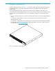
1 General Description The HP 8/20q Fibre Channel Switch (Figure 1) is a 20-port, 8-Gb/s switch with both Ethernet and serial management interfaces. This chapter describes the features and capabilities of the HP 8/20q Fibre Channel Switch. You can manage fabrics with the Command Line Interface (CLI), the QuickTools web applet, or the optional Enterprise Fabric Management Suite.
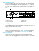
Switch LEDs and controls The switch LEDs provide information about the switch’s operational status. These LEDS include the Input Power LED (green), Heartbeat LED (green), and the System Fault LED (amber) (Figure 2). For information about port LEDs, see ”Port LEDs” (page 10). The Maintenance button (Figure 2) is the only switch control. It is used to reset a switch or to recover a disabled switch.
Maintenance button The Maintenance button (Figure 2) is a dual-function momentary switch on the front panel. Its purpose is to reset the switch or to place the switch in maintenance mode. Maintenance mode sets the IP address to 10.0.0.1 and provides access to the switch for maintenance purposes when flash memory or the resident configuration file is corrupted. For more information, see ”Recovering a switch using maintenance mode” (page 53).
Fibre Channel ports The 8/20q Fibre Channel Switch has twenty Fibre Channel ports. Ports are numbered 0–19 (Figure 3). Each of the ports is served by a Small Form-Factor Pluggable (SFP+) transceiver and is capable of 8-Gb/s, 4-Gb/s, or 2-Gb/s transmission. • SFPs are hot-pluggable. • User ports can self-discover both the port type and transmission speed when connected to devices or other switches.
Port Activity LED (green) The Activity LED indicates that data is passing through the port. Each frame that the port transmits or receives illuminates this LED for 50 milliseconds. This makes it possible to observe the transmission of a single frame. Transceivers The 8/20q Fibre Channel Switch supports SFP+ optical transceivers for the Fibre Channel ports. A transceiver converts electrical signals to and from optical laser signals to transmit and receive data.
Ethernet port The Ethernet port is an RJ-45 connector that provides a connection to a workstation through a 10/100 Base-T Ethernet cable (Figure 5). A workstation can be a Windows or a Linux server that is used to configure and manage the switch fabric. An Ethernet connection to the switch is required to manage the switch using the CLI, QuickTools, Enterprise Fabric Management Suite, SAN Connection Manager, or Simple Network Management Protocol (SNMP).
The serial port connector requires a null-modem F/F DB9 cable. The pins on the switch RS-232 connector (Figure 6) are identified in Table 2. For information about connecting the workstation through the serial port, see ”Connect the management station or workstation to the switch” (page 37).
QuickTools web applet QuickTools is a browser-based graphical user interface (GUI) that provides switch management capabilities beyond those of SAN Connection Manager. You run QuickTools by opening the switch IP address with an internet browser on your workstation. See the HP 8/20q Fibre Channel Switch QuickTools Switch Management User Guide.
Storage Management Initiative–Specification (SMI-S) SMI-S provides for the management of the switch through third-party applications that use the SMI-S. For more information, see the HP 8/20q and SN6000 Fibre Channel Switch CIM Agent Reference Guide. File transfer protocols FTP and TFTP provide the command line interface for exchanging files between the switch and the workstation. These files include firmware image files, configuration files, and log files.
2 Planning a Fabric This chapter contains information about planning a fabric. Devices When planning a fabric, consider the following: • The number of devices and the anticipated demand. This will determine the number of ports that are needed and in turn the number of switches. • The transmission speeds of your HBAs and SFPs. The switch supports 2-Gb/s, 4-Gb/s and 8-Gb/s transmission speeds. IMPORTANT: Setting a Fibre Channel port that has an 8-Gb/s SFP transceiver to 1-Gb/s will down the port.
Table 3 Zoning database limits (Continued) Limit Description MaxMembersPerZone Maximum number of members in a zone (2,000). MaxMembersPerAlias Maximum number of members in an alias (2,000) Performance The 8/20q Fibre Channel Switch supports class 2 and class 3 Fibre Channel service at transmission rates of 8-Gb/s with a maximum frame size of 2,148 bytes.
Bandwidth Bandwidth is a measure of the volume of data that can be transmitted at a given transmission rate. A Fibre Channel port can transmit or receive at nominal rates of 8 Gb/s, 4 Gb/s, or 2 Gb/s depending on the device to which it is connected. This corresponds to full duplex bandwidth values of 1,700 MB, 850 MB, and 424 MB respectively. Multiple source ports can transmit to the same destination port if the destination bandwidth is greater than or equal to the combined source bandwidth.
Feature licenses License keys provide a way to expand the capabilities of your switch and fabric as your needs grow. The HP 8/20q 4-port Upgrade License activates additional Fibre Channel ports to 12, 16, or 20 ports. Applying a license key is not disruptive, nor does it require a switch reset. To order a license key, contact your switch distributor or your authorized reseller. For more information, see ”Installing feature license keys” (page 42).
Domain ID, principal priority, and domain ID lock The following switch configuration settings affect multiple switch fabrics: • Domain ID • Principal priority • Domain ID lock The domain ID is a unique number from 1–239 that identifies each switch in a fabric. The principal priority is a number (1–255) that determines the principal switch which manages domain ID assignments for the fabric. The switch with the highest principal priority (1 is high, 255 is low) becomes the principal switch.
You can connect multiple 8/20q Fibre Channel Switches to one or more remote fabrics using multiple TR_Ports. Local and remote devices are identified by their respective port worldwide names. Consider the following mapping rules: • A TR_Port can support a maximum of 32 local device/remote device mappings. • A specific local device can be mapped to devices on only one remote fabric. Local devices on the same 8/20q Fibre Channel Switch can each be mapped to different remote fabrics.
3. Map local devices to remote devices and activate the connection. The mapping process creates an inter-fabric zone (IFZ) in the active zoneset consisting of the local device, the remote device, and the TR_Port. When the mapping is complete, the new zoneset is activated. The name of the inter-fabric zone begins with IFZ followed by the lowest device port WWN followed by the remaining port WWN, all uppercase, separated by underscores (_).
• Management Server (MS): Enables or disables the management of the switch through third-party applications that use FC-GS-3 Management Server. The default is disabled. • Call Home: If enabled and configured, switches can send alerts regarding events and faults to Email addresses. Users can configure the type of events and where the alerts are sent. IMPORTANT: The Call Home service provides an e-mail notification capability for the switch.
Security Security is available at the following levels: • User account security, page 25 • IP security, page 25 • Port binding, page 26 • Connection security, page 26 • Device security, page 26 User account security User account security consists of the administration of account names, passwords, expiration date, and authority level.
Consider your IP security requirements and the type of encryption you want to use (public key or secret). Also consider which of the connected devices support IKE, and how you will configure IP security on both the switch and connected devices. Port binding Port binding provides authorization for a list of up to 32 switch and device WWNs that are permitted to log in to a particular switch port. Switches or devices that are not among the 32 are refused access to the port.
the security database for the entire fabric resides on the server. In this way, the security database can be managed centrally, rather than on each switch. You can configure up to five RADIUS servers to provide failover. You can configure the RADIUS server to authenticate just the switch or both the switch and the initiator device if the device supports authentication. When using a RADIUS server, every switch in the fabric must have a network connection.
3 Installation This chapter describes how to install and configure the switch. Site requirements Consider the following items when installing an 8/20q Fibre Channel Switch. Management Station and Workstation requirements The management station requirements for SAN Connection Manager and Enterprise Fabric Management Suite are described in Table 7. Workstation requirements for QuickTools are described in Table 8.
Table 8 Workstation requirements for QuickTools Internet Browser Microsoft Internet Explorer 6.0 or later Netscape Navigator 6.0 and later Firefox 1.5 and later Java Runtime Environment 1.4.2 or later1 Hardware RJ-45 Ethernet port 1. You must disable caching of temporary files and applets in Java to prevent conflicts with past or future versions of QuickTools. Furthermore, you may need to disable caching again after upgrading Java.
Mount the switch The switch can be placed on a flat surface and stacked, or mounted in a 19” Electronics Industries Association (EIA) rack. See ”Weight and physical dimensions” (page 69) for weight and dimensional specifications. Adhesive rubber feet are provided for surface mounts only. Without the rubber feet, the switch occupies 1U of space in an EIA rack.
Collect the required items NOTE: The rack mount kit installation requires one technician. Locate the following items and set them aside: • 8/20q Fibre Channel Switch • 8/20q and SN6000 Fibre Channel Switch rack-mount kit • Smaller items, such as screws, ship in plastic bags in the kit. See Table 9.
Rack the switch 1. Remove and discard the four 10-32 screws from the sides of the switch. 2. Attach each rail to the switch using two 10-32 x .375-inch screws with captive washers (Figure 7). Make sure the slotted ends of the rails are on the power-supply side (not the SFP-port side) of the switch. Figure 7 Attaching the rails to the switch 3. On the rack vertical posts, mark the holes that will be used by the rail flanges (three on each rear vertical post, two on each front vertical post).
5. Fasten each rail flange to the front of the rack using two M6 machine screws (Figure 10). Figure 10 Fastening the rail to the front of the rack 6. Fasten each slotted-rail end to the rear mounting bracket using a flat washer and a 1/4-20 hex nut (Figure 11). Figure 11 Fastening the rail to the rear mounting bracket 7. Optional: Fasten the filler panel to the rear mounting brackets with two M6 machine screws (Figure 12).
Install the transceivers A small form-factor pluggable (SFP) transceiver is required for each switch port that will be connected to a device or another switch. SFPs are not included with the switch. Only HP SFPs are supported for use in the switch. To install an SFP transceiver, insert the transceiver into any of the active switch ports and gently press until it snaps in place. TIP: The transceiver will fit only one way.
For a Linux workstation: a. Set up minicom to use the serial port. Create or modify the /etc/minirc.dfl file with the following content. pr pu pu pu portdev/ttyS0 minit mreset mhangup b. Verify that all users have permission to run minicom. Review the /etc/minicom.users file and confirm that the line ALL exists or that there are specific user entries. Apply power to the switch WARNING! This product is supplied with a 3-wire power cable and plug for the user’s safety.
Connect the management station or workstation to the switch You can manage the switch using the SAN Connection Manager, QuickTools, Enterprise Fabric Management Suite, or the CLI. SAN Connection Manager requires at least one FC connection and an Ethernet connection to the switch. QuickTools and Enterprise Fabric Management Suite require an Ethernet connection to the switch. The CLI can use an Ethernet connection or a serial connection. • If this switch is part of the 8Gb SAN Connection Kit installation: a.
QuickTools switch configuration To log in and configure the switch using QuickTools: 1. Open an Internet browser and enter the default IP address 10.0.0.1 to start the QuickTools web applet. 2. Log in to the switch using the default user name (admin) and password (password). 3. Obtain the IP address and subnet mask from your network administrator. 4. Open the QuickTools Wizards menu and select Configuration Wizard. Follow the instructions to set the IP address and the password.
Cable devices to the switch Connect cables to the SFP transceivers and their corresponding devices, and then energize the devices. Device host bus adapters can have SFP (or SFF) transceivers. Duplex cable connectors are keyed to ensure proper orientation. Choose the Fibre Channel cables with the connector combination that matches the device host bus adapter. GL_Ports self configure as FL_Ports when connected to loop of devices or F_Ports when connected to a single device.
Using QuickTools to install firmware To install firmware using QuickTools: 1. In the faceplate display, open the Switch menu and select Load Firmware. 2. In the Load Firmware dialog, choose one of the following: • Select a firmware image file from the Version drop-down list. • Click Browse to change the folder (path) to search for firmware image files. Click Rescan to search the new folder displayed in the Firmware Image Folder field. 3. Click Start to begin the firmware load process.
3. Enter your account name on the remote host (FTP only) and the IP address of the remote host. When prompted for the source file name, enter the path for the firmware image file. User Account : johndoe IP Address : 10.20.20.200 Source Filename : 8.0.4.xx.xx_epc About to install image. Do you want to continue? [y/n] y 4. When prompted to install the new firmware, enter y to continue or n to cancel. Entering y will disrupt traffic. This is the last opportunity to cancel. About to install image.
Adding a switch to an existing fabric If there are no special conditions to be configured for the new switch, plug in the switch. The switch becomes functional with the default fabric configuration. The default fabric configuration settings are as follows: • Fabric zoning is sent to the switch from the fabric. • All ports will be GL_Ports. • The default IP address 10.0.0.
Role of the Remote Support Software Manager When you install RSP, Remote Support Software Manager (RSSWM) is also installed on your CMS. RSSWM downloads required and recommended software components, including the required software components listed below, which are used to allow communication with HP Services, contract and warranty entitlement capabilities and to provide on-site analysis.
Supported Web browsers: • Internet Explorer, Version 6.0 and 7.0 • Mozilla, Versions 1.5, 1.6, and 1.7 • Firefox, Versions 1.0.2, 1.5, and 2.0 Applications: • Java Virtual Machine plug-in for Internet Explorer NOTE: Java plug-in is not installed by default in the Internet Explorer Web Browser for 32-bit and x64 editions of Windows Server 2003.
i. In the Trap Community field, enter the trap community name. The name can be up to 32 characters and must agree with the community name used in the OSEM application. The following characters may not be used in the user-defined fields: pound sign (#), semi-colon (;), and comma (,). j. Click OK to enable the changes. For more information about QuickTools, see the HP 8/20q Fibre Channel Switch QuickTools Switch Management User Guide. To configure an SNMP trap using the CLI: a.
4 Diagnostics and Troubleshooting Diagnostic information about the switch is available through the switch LEDs and the port LEDs. Diagnostic information is also available through the CLI, QuickTools, Enterprise Fabric Management Suite, or SAN Connection Manager event logs and error displays. This chapter also describes using maintenance mode to recover a disabled switch. See ”Recovering a switch using maintenance mode” (page 53).
Power-On self test diagnostics The switch performs a series of tests as part of its power-up procedure. The POST diagnostic program performs the following tests: • Checksum tests on the boot firmware in Programmable read-only memory (PROM) and the switch firmware in flash memory • Internal data loopback test on all ports • Access and integrity test on the Application-specific integrated circuit (ASIC) During the POST, the switch logs any errors encountered. Some POST errors are critical, others are not.
Configuration file system error blink pattern A configuration file system error blink pattern is 4 blinks followed by a 2-second pause. The 4-blink error pattern indicates that a configuration file system error has occurred, and that the configuration file must be restored. 2 seconds To restore the switch configuration: 1. Establish communications with the switch using Telnet. Enter one of the following on the command line: telnet xxx.xxx.xxx.xxx or telnet switchname where xxx.xxx.xxx.
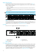
Logged-in LED indications Port diagnostics are indicated by the Logged-in LED for each port (Figure 15). 1 2 1 Logged-in LED (port 0) 2 Logged-in LED (port 10) Figure 15 Logged-in LED The Logged-in LED has three indications: • Continuous illumination: A device is logged in to the port. • Flashing once per second: A device is logging in to the port, or the port is in the diagnostics state. • Flashing twice per second: The port is down, offline, or an error has occurred.
3. Display the fabric domain IDs using the show domains CLI command or by selecting the QuickTools Switch tab, Summary icon. Are all domain IDs in the fabric unique? • Yes—Continue. • No—Correct the domain IDs on the offending switches using the set config switch CLI command or the QuickTools Switch Properties dialog. Reset the port. If the condition remains, continue. 4.
Review the event browser to determine if excessive port errors are responsible for disabling the port. Look for a message that mentions one of the monitored error types indicating that the port has been disabled, then perform the following procedure: 1. Examine the alarm configuration for the associated error using the show config threshold CLI command. See the show config threshold CLI command in the HP 8/20q Fibre Channel Switch Command Line Interface Guide.
Recovering a switch using maintenance mode A switch can become inoperable or unmanageable for the following reasons: • Firmware becomes corrupt • IP address is lost • Switch configuration becomes corrupt • Password is forgotten In these specific cases, you can recover the switch using maintenance mode. Maintenance mode temporarily returns the switch IP address to 10.0.0.
Unpacking a firmware image file in maintenance mode (option 1) The Image Unpack option unpacks and installs new firmware when the current firmware has become corrupt. Before using this option, you must load the new firmware image file onto the switch. To install new firmware using this option: 1. Place the switch in maintenance mode. See the procedure for maintenance mode in ”Recovering a switch using maintenance mode” (page 53). 2. Use FTP to load a new firmware image file onto the switch.
Resetting the switch in maintenance mode (option 7) The Reset Switch option closes the Telnet session, exits maintenance mode, and reboots the switch using the current switch configuration. All unpacked firmware image files that reside on the switch are deleted. Updating the boot loader in maintenance mode (option 8) The Update Boot Loader option updates the system boot loader which loads the Linux kernel into memory. Use this option only at the direction of your authorized maintenance provider.
5 Support and Other Resources Document conventions and symbols Document conventions Table 10 Convention Element Medium blue text: Figure 1 Cross-reference links and email addresses Medium blue, underlined text (http://www.hp.
Contacting HP HP contact information For HP technical support: • In the United States, see the Contact HP United States webpage: (http://welcome.hp.com/country/us/en/contact_us.html). To contact HP by phone, call: 1-800-HP-INVENT (1-800-474-6836). This service is available 24 hours a day, 7 days a week. For continuous quality improvement, calls may be recorded or monitored. • In other locations, see the Contact HP worldwide (in English) webpage: (http://www.hp.com/country/us/en/wwcontact.html).
• HP 8/20q and SN6000 Fibre Channel Switch Command Line Interface Quick Reference Guide • HP 8/20q and SN6000 Enterprise Fabric Management Suite User Guide • HP SAN Connection Manager User Guide • HP 8/20q an SN6000 Fibre Channel Switch Event Messages Reference Guide • HP 8/20q and SN6000 Fibre Channel Switch Simple Network Management Protocol Reference Guide • HP 8/20q and SN6000 Fibre Channel Switch CIM Agent Reference Guide For the latest product information, including firmware, documentation, and suppor
A Regulatory Compliance and Safety Regulatory compliance Federal Communications Commission notice for Class A equipment This equipment has been tested and found to comply with the limits for a Class A digital device, pursuant to Part 15 of the FCC Rules. These limits are designed to provide reasonable protection against harmful interference when the equipment is operated in a commercial environment.
Certification and classification information This product contains a laser internal to the fiber optic (FO) transceiver for connection to the Fibre Channel communications port. In the USA, the FO transceiver is certified as a Class 1 laser product conforming to the requirements contained in the Department of Health and Human Services (DHHS) regulation 21 CFR, Subchapter J. A label on the plastic FO transceiver housing indicates the certification.
European Union regulatory notice This product complies with the following Eurupean Union (EU) directives: • Low Voltage Directive 2006/95/EC • EMC Directive 2004/108/EC Compliance with these directives implies conformity to applicable harmonized European standards (European norms), which are listed on the EU Declaration of Conformity issued by Hewlett-Packard for this product or product family.
Chinese warning messages Altitude warning message 仅适用于海拔 2000 米以下地区安全使用 May be used safely only in areas where the altitude is less than 2000m. Non-tropical warning message 仅适用于非热带气候条件下安全使用 May be used safely only in non-tropical climates.
B How to Prevent Electrostatic Discharge To prevent damage to the system, you must follow certain precautions when setting up the system or handling parts. A discharge of static electricity from a finger or other conductor may damage system boards or other static-sensitive devices. This type of damage may reduce the life expectancy of the device. To prevent electrostatic damage, observe the following precautions: • Avoid hand contact by transporting and storing products in static-safe containers.
C Technical Specifications This appendix contains the specifications for the 8/20q Fibre Channel Switch. See ”General Description” (page 7) for the location of all connections, switches, controls, and components. General specifications Table 11 lists general specifications for the 8/20q Fibre Channel Switch. Table 11 General specifications for the 8/20q Fibre Channel Switch Specification Description Fibre Channel protocols FC-PH Rev. 4.3 FC-PH-2 FC-PH-3 FC-AL Rev 4.6 FC-AL-2 Rev 7.
Table 11 General specifications for the 8/20q Fibre Channel Switch (Continued) Specification Description Maximum user ports > 475,000 ports depending on configuration. For the latest supported configurations, see the SAN Design Reference Guide available at http://www.hp.com/go/SANdesignguide. Buffer credits 16 buffer credits per port, ASIC embedded memory Media type SFP optical transceiver Fabric port speed 2.125, 4.250, 8.
Fabric management specifications Table 13 Fabric management specifications for the 8/20q Fibre Channel Switch Specification Description Management methods Command Line Interface FTP GS-3 Management Server SAN Connection Manager graphical user interface QuickTools web applet SMI-S SNMP TFTP Maintenance connection RS-232 connector; null modem F/F DB9 cable Ethernet connection RJ-45 connector; 10/100 BASE-T cable Switch agent Allows a network management station to obtain configuration values, traffi
Environmental requirements To ensure proper operation, the switch must not be subjected to environmental conditions beyond those for which it was tested. The ranges specified in Table 16 identify the acceptable environment for both operating and non-operating conditions.
D Factory Configuration Defaults This appendix describes the factory configuration defaults: Factory switch configuration Enter the show config switch CLI command to display switch configuration values.
Factory port configuration Enter the show config port CLI command to display port configuration values.
Factory port threshold alarm configuration Enter the show config threshold CLI command to display threshold alarm configuration values. If the ThresholdMonitoringEnabled parameter is disabled (False), none of the individual threshold monitoring parameter settings can be applied.
Factory SNMP configuration Enter the show setup snmp CLI command to display SNMP configuration values. Table 21 SNMP configuration defaults Parameter Default SNMPEnabled True Contact Location Description HP 8/20q Fibre Channel Switch ObjectID 1.3.6.1.4.1.3873.1.11 AuthFailureTrap False ProxyEnabled True SNMPv3Enabled False Trap [1-5] Address Trap 1: 10.0.0.254 Traps 2–5: 0.0.0.
Factory DNS host name configuration Enter the show setup system dns CLI command to display the Domain Name System host name configuration values.
Factory event logging configuration Enter the show setup system logging CLI command to display the event logging configuration values. Table 26 Event logging configuration defaults Parameter Default LocalLogEnabled True RemotelogEnabled False RemoteLogHostAddress 10.0.0.254 Factory NTP server configuration Enter the show setup system ntp CLI command to display the NTP server configuration values.
Factory RADIUS configuration Enter the show setup radius CLI command to display RADIUS configuration values. Table 29 RADIUS configuration defaults Parameter Default DeviceAuthOrder Local UserAuthOrder Local TotalServers 0 DeviceAuthServer False UserAuthServer False AccountingServer False ServerIPAddress 10.0.0.
Factory Call Home configuration Enter the show setup callhome CLI command to display call home configuration values. Table 31 78 Call Home service configuration defaults Parameters Default PrimarySMTPServerAddr 0.0.0.0 PrimarySMTPServerPort 25 PrimarySMTPServerEnabled False SecondarySMTPServerAddr 0.0.0.0 SecondarySMTPServerPort 25 SecondarySMTPServerEnabled False ContactEmailAddress nobody@localhost.
Glossary This glossary defines terms used in this guide or related to this product. It is not a comprehensive glossary of computer terms. 4-port Upgrade License A licensed feature that enables you to activate additional FC ports. Active firmware The firmware image on the switch that is in use. Active zoneset The zoneset that defines the current zoning for the fabric. See Zoneset. Activity LED A port LED that indicates when frames are entering or leaving the port.
Fabric device An interface by which device host bus adapters (HBAs) can be managed through the management interface fabric. (FDMI) Fabric management switch The switch through which the fabric is managed. Fabric security A feature that provides security for fabric users and devices, including user account security and fabric services. See Device security and Fabric services. Fabric services A component of fabric security that provides for the control of inband management and SNMP on a switch.
Maintenance mode Maintenance mode sets the IP address to 10.0.0.1 and provides access to the switch for maintenance purposes. Management A set of guidelines and definitions for SNMP functions. See Simple Network Management Information Base (MIB) Protocol (SNMP). Management station Workstation or server used to run SAN Connection Manager. N_Port Node port. A Fibre Channel device port in a point-to-point or fabric connection.
Workstation PC or Linux workstation that manages the switch using QuickTools or the command line interface (CLI). Worldwide Name (WWN) A unique 64-bit address assigned to a device by the device manufacturer. Zone A set of ports or devices grouped together to control the exchange of information. Zoneset A set of zones grouped together. The active zoneset defines the zoning for a fabric. See Zone. Zoning database The set of zonesets, zones, and aliases stored on a switch.
Index Numerics 10/100 Base-T straight cable 37 A account name default 38 FTP 41 maintenance mode 53 active zone set 17 Activity LED 11, 12 air flow 68 alias 17 altitude 70 association 25 authority 25 authorization 26 B bandwidth 19, 68 boot loader 55 browser 29, 30 buffer credit 18, 68 C cable 10/100 Base-T 37 10/100 Base-T crossover 37 null modem F/F DB9 37 cable length 18 Call Home service configure to HP service 42 description 24 certificate 25, 26 certificate authority 25 classes of service 67 comman
install with CLI 40 install with QuickTools 40 non-disruptive activation 39 unpack image 54 FL_Port 11 flash memory 9 frame size 68 FRU - See Field Replaceable Unit FTP - See File Transfer Protocol G G_Port 11 generic ports 11 GL_Port 11 H hardware requirements 29, 30 HBA - See Host Bus Adapter Heartbeat LED 8, 48 heat output 69 help, obtaining 58, 59 HP services 42 storage website 59 Subscriber’s choice website 58 technical support 58 humidity 30, 70 HyperTerminal application 35 I IKE - See Internet Key
SNMP - See Simple Network Management Protocol soft zone 17 SSH - See Secure Shell SSL - See Secure Socket Layer Storage Management Initiative-Specification 15 Subscriber’s choice, HP 58 surface mount 31 switch add to fabric 42 air flow 68 configuration 37 diagnostics 47 management 13 management service 23 power up 36 recovery 53 reset 9, 55 services 23 shock 70 specifications 67 upgrade 10 vibration 70 symbols in text 57 System Fault LED 8, 47 system processor 68 types 11, 67 POST - See Power-on self test
HP storage 59 HP Subscriber’s choice 58 workstation configuration 35 connecting 37 IP address 35 operating system 12 requirements 29 Z zone conflict 51 definition 17 zone set active 17 definition 17 zoning database 17 hardware-enforced 17 limits 17 86