Installation Guide K Class HP 9000 Enterprise Servers Part No.
Legal Notices The information contained in this document is subject to change without notice. Hewlett-Packard makes no warranty of any kind with regard to this material, including, but not limited to, the implied warranties of merchantability and fitness for a particular purpose. Hewlett-Packard shall not be liable for errors contained herein or direct, indirect, special, incidental or consequential damages in connection with the furnishing, performance, or use of this material. Restricted Rights Legend.
Printing History New editions of this manual incorporate all material updated since the previous edition. The manual printing date and part number indicate its current edition. The printing date changes when a new edition is printed. (Minor corrections and updates which are incorporated at reprint do not cause the date to change.) The manual part number changes when extensive technical changes are incorporated. February 1995....................................................................................
Preface This edition of the HP 9000/Kxx0 Installation Guide contains technical information about HP 9000 Computers.
Introduction This Installation Guide illustrates the procedures for installing the HP 9000 K Class computers. The contents of this guide include: 1. Overview of System Installation - a brief description of the installation procedure. 2. Overview of System Power/Data Cabling - A reference figure showing the basic power and data connections for the core system (Computer and Console). 3. Installation Steps - A series of figures showing each step in the installation process.
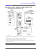
Introduction Overview of System Installation Overview of System Installation 1. Standard Console, Keyboard, and Optional Uninterruptible Power System (UPS): a. Connect the console data cable to the "Console" port on the core I/O card of the computer. b. Plug the standard console power cable into a UPS power receptacle. c. Connect the keyboard cable to the keyboard connector on the console. d.
Introduction Overview of System Installation Optional Graphics Console If desired, a graphics console and mouse can be connected to the SPU instead of the standard console. To install the graphics console, substitute the following Step 1 for the standard Step 1 in the installation procedure listed above: Optional Graphics Console: A4032A/A4033A/A4331A Graphics Display with Keyboard and Mouse: 1. Connect the graphics console data cable to the "OPTIONAL I/O" port on the system core I/O card. 2.
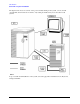
Introduction Overview of System Installation The figure below shows an overview of the power and data cabling for the system, console, and the optional UPS, and is intended for reference only. Cable part numbers may not be the same for all systems. To proceed with actual installation of the system, start at the page titled "Standard Console, Keyboard, and Optional UPS".
Introduction Standard Console, Keyboard, and Optional UPS Standard Console, Keyboard, and Optional UPS A. (K100/K200/K210/K220/K400/K410/K420) 1. Connect the standard console data cable to the "Console" port on the core I/O board of the system. 2. Plug the standard console power cable into a UPS power receptacle. 3. Connect the keyboard cable to the keyboard connector on the console. 4. Connect the UPS data cable between the "UPS" connector on the system and the appropriate data connector on the UPS.
Introduction Optional Graphics Console: A4032A/A4033A/A4331A Graphics Display with Keyboard and Mouse Optional Graphics Console: A4032A/A4033A/A4331A Graphics Display with Keyboard and Mouse NOTE 6 An A4032A or A4033A Graphics Console may be connected to the system instead of the standard console.
Introduction Optional Graphics Console: A4032A/A4033A/A4331A Graphics Display with Keyboard and Mouse 1. Connect the graphics console data cable to the "OPTIONAL I/O" port on the system core I/O card. 2. Plug the graphics console power cable into a UPS power receptacle. 3. Connect the keyboard cable to the keyboard connector on the system core I/O card. 4. Connect the mouse cable to the connector labeled "MOUSE" on the system core I/O card. 5.
Introduction Standard Console, Keyboard, and Optional UPS Standard Console, Keyboard, and Optional UPS (K250/K260/K360/K370/K380/K450/K460/K570/K580) 1. Connect the standard console data cable to the "Console" port on the system core I/O card. 2. Plug the standard console power cable into a UPS power receptacle. 3. Connect the keyboard cable to the keyboard connector on the system core I/O board. 4. Connect the mouse cable to the connector labeled "MOUSE" on the system core I/O board. 5.
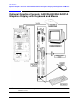
Introduction Local Area Network (LAN), Fast/Wide Differential SCSI, and Parallel Device Cabling Local Area Network (LAN), Fast/Wide Differential SCSI, and Parallel Device Cabling 1. Connect the LAN to either the "10BASE-T" or "AUI" connector on the core I/O card. 2. Connect a Fast/Wide Differential SCSI cable or terminator to the "F/W DIFF. SCSI" connector on the core I/O card. 3. Connect an optional parallel device (such as a printer) to the connector labeled "PARALLEL" on the core I/O card.
Introduction Internal or External Modem, and MDP Internal or External Modem, and MDP 1. Connect a line access module to the "INTERNAL MODEM" connector on the core I/O card. 2. If not using the internal modem, connect the external modem to the "EXTERNAL MODEM" connector on the core I/O card. 3. Connect the Modem Distribution Panel (MDP) to the "MDP" connector on the core I/O card.
Introduction Summary of System Connections Summary of System Connections The figure above is a summary of all the system connections previously described. You should use this figure to make a quick check of all connections you have made to ensure that they are correct before connecting power cabling.
Introduction Stabilizer Block (Chock Block) Stabilizer Block (Chock Block) The stabilizer block (or chock block) is used to prevent the system cabinet from being inadvertently moved around. The block can be placed under either the front or rear wheels. 1. Position the stabilizer block at the desired location for the system cabinet. 2. Roll the system cabinet onto the stabilizer block until the front (or rear) wheels fall into the notch in the stabilizer block.
Introduction Power Connections Power Connections If you are using an Uninterruptible Power System (UPS): 1. Plug the convenience power cable (8120-6371) into the power receptacle closest to the upper-left corner of the UPS. 2. Plug the UPS power cable into wall power. If you are NOT using a UPS: Connect the system power cable (8120-5337) directly to wall power.
Introduction POWER ON: First, Turn On the UPS and All Peripherals POWER ON: First, Turn On the UPS and All Peripherals 1. Turn on the UPS. 2. Turn on all system peripherals. Be sure all system peripherals are on with no error indications.
Introduction Then, Turn On the System Then, Turn On the System 1. Turn on the system by setting the key switch to the "ON" position. 2. Refer to the Owner’s Guide for that came with your system for operator information.
Introduction Then, Turn On the System 16