Installation Guide HP 9000 rp3410 and HP 9000 rp3440 Manufacturing Part Number: A7137-96007 Seventh Edition April 2007 Printed in the US
Legal Notices Copyright Notices. © Copyright 2007 Hewlett-Packard Development Company, L.P. The information contained herein is subject to change without notice. The only warranties for HP products and services are set forth in the express warranty statements accompanying such products and services. Nothing herein should be construed as constituting an additional warranty. HP shall not be liable for technical or editorial errors or omissions contained herein. Printed in U.S.A.
Contents About This Document 1. Installing the System Introduction . . . . . . . . . . . . . . . . . . . . . . . . . . . . . . . . . . . . . . . . . . . . . . . . . . . . . . . . . . . . . . . . . . . . . . . . Server Views . . . . . . . . . . . . . . . . . . . . . . . . . . . . . . . . . . . . . . . . . . . . . . . . . . . . . . . . . . . . . . . . . . . . . . Detailed Server Description . . . . . . . . . . . . . . . . . . . . . . . . . . . . . . . . . . . . . . . . . . . . . . . . . . . . . . . . . .
Contents Additional Setup . . . . . . . . . . . . . . . . . . . . . . . . . . . . . . . . . . . . . . . . . . . . . . . . . . . . . . . . . . . . . . . . . . . Accessing the Host Console . . . . . . . . . . . . . . . . . . . . . . . . . . . . . . . . . . . . . . . . . . . . . . . . . . . . . . . . . . . . Accessing the Host Console With the TUI - CO Command . . . . . . . . . . . . . . . . . . . . . . . . . . . . . . . . . Interacting with the iLO MP Using the Web GUI . . . . . . . . . . . . . . . . . . . .
Tables Table 1. Publishing History Details . . . . . . . . . . . . . . . . . . . . . . . . . . . . . . . . . . . . . . . . . . . . . . . . . . . 9 Table 2. HP-UX 11i Releases . . . . . . . . . . . . . . . . . . . . . . . . . . . . . . . . . . . . . . . . . . . . . . . . . . . . . . . . 11 Table 1-1. HP 9000 rp3410 and rp3440 Server Features. . . . . . . . . . . . . . . . . . . . . . . . . . . . . . . . . . 16 Table 1-2. Server Dimensions and Values. . . . . . . . . . . . . . . . . . . . . . . . . . . . . .
Tables 6
Figures Figure 1-1. HP 9000 rp3410/rp3440 Server (Front View) . . . . . . . . . . . . . . . . . . . . . . . . . . . . . . . . . Figure 1-2. HP 9000 rp3410/rp3440 Server (Front View with Bezel Removed) . . . . . . . . . . . . . . . . Figure 1-3. HP 9000 rp3410/rp3440 Server (Rear View) . . . . . . . . . . . . . . . . . . . . . . . . . . . . . . . . . . Figure 1-4. HP 9000 rp3410/rp3440 Server (Pedestal Mount) . . . . . . . . . . . . . . . . . . . . . . . . . . . . . Figure 1-5. Front View . . . . . . . . . .
Figures Figure 1-44. Locking the Dual Processor Module in Place . . . . . . . . . . . . . . . . . . . . . . . . . . . . . . . . Figure 1-45. Slide the Sequencing Retainer Plate . . . . . . . . . . . . . . . . . . . . . . . . . . . . . . . . . . . . . . Figure 1-46. Secure the Captive Screws . . . . . . . . . . . . . . . . . . . . . . . . . . . . . . . . . . . . . . . . . . . . . . Figure 1-47. Power Module Shims . . . . . . . . . . . . . . . . . . . . . . . . . . . . . . . . . . . . . . . . . . . . . . . .
About This Document This document describes how to unpack the HP 9000 rp3410/rp3440 server, install additional components, start a server console session, power on the server, and boot the operating system. The document printing date and part number indicate the document’s current edition. The printing date changes when a new edition is printed. Minor changes may be made at reprint without changing the printing date. The document part number changes when extensive changes are made.
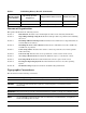
Table 1 Publishing History Details (Continued) Document Manufacturing Part Number Operating Systems Supported Supported Product Versions Publication Date A7137-96001 HP-UX 11i v1 HP 9000 rp3410 and rp3440 April 2005 N/A HP-UX 11i v1 HP 9000 rp3410 and rp3440 July 2004 Document Organization This guide is divided into the following sections. Section 1 Introduction: Provides views and descriptions of the server and safety information.
TIP Tips provide you with helpful hints for completing a task. A tip is not used to give essential information, but can be used, for example, to provide an alternate method for completing the task that precedes it. Book Title The title of a book. On the Web and on the Instant Information CD, it may be a hot link to the book itself. KeyCap The name of a keyboard key or graphical interface item (such as buttons, tabs, and menu items). Note that Return and Enter both refer to the same key.
Server Hardware Information: http://docs.hp.com/hpux/hw/ Diagnostics and Event Monitoring: Hardware Support Tools Complete information about HP’s hardware support tools, including online and offline diagnostics and event monitoring tools, is at the http://docs.hp.com/hpux/diag/ Web site. This site has manuals, tutorials, FAQs, and other reference material. Web Site for HP Technical Support: http://us-support2.external.hp.com/ Books about HP-UX Published by Prentice Hall The http://www.hp.
1 Installing the System This chapter provides information on how to install the system.
Installing the System Introduction Server Views Figure 1-1, Figure 1-2, Figure 1-3, and Figure 1-4 show the front, rear, and pedestal-mount views of the HP 9000 rp3410 and rp3440 servers.
Installing the System Introduction Figure 1-4 Chapter 1 HP 9000 rp3410/rp3440 Server (Pedestal Mount) 15
Installing the System Introduction Detailed Server Description The following sections list the main subsystems within the HP 9000 rp3410 and rp3440 servers. Features Table 1-1 lists the features of the HP 9000 rp3410 and rp3440 servers. Table 1-1 Features HP 9000 rp3410 and rp3440 Server Features rp340 rp3440 PA-8800 Processors One or two processors at 800 MHz with 1.5 MB L1 cache/32 MB L2 cache One to four processors at 800 MHz (or 1 GHz) and 1 GHz with 1.
Installing the System Introduction Firmware Firmware consists of many individually linked binary images that are bound together by a single framework at run time. Internally, the firmware employs a software database called a device tree to represent the structure of the hardware platform and to provide a means of associating software elements with hardware functionality. The firmware incorporates Boot Console Handler (BCH) which provides an interface between the operating system and the platform firmware.
Installing the System Introduction • If installing a hot-pluggable component, complete the required software intervention prior to removing the component. • If installing an assembly that is neither hot-swappable, nor hot-pluggable, disconnect the power cable from the external server power receptacle.
Installing the System Introduction Figure 1-6 Control Panel Locator Button and LED Diagnostics LEDs (Disabled) 1 2 3 4 LAN Power Button LED Power System On/Off LED LED LAN System Additional Controls and Indicators The HP 9000 rp3410 or HP 9000 rp3440 server can have up to three low-voltage differential (LVD), 3.5 inch form factor hard disk drives (HDDs) installed. These hard disk drives have LEDs that provide status and activity information.
Installing the System Introduction Optional Removable Media Drive The HP 9000 rp3410 or rp3440 server is delivered without a removable media drive. Either a DVD or CD-RW/DVD, drive may be added. Each of these optional devices has one activity LED. Figure 1-8 DVD–ROM or CD-RW/DVD-ROM LED Indicators DVD Activity LED Eject Button Emergency Eject Table 1-4 lists the DVD drive LED definitions.
Installing the System Introduction Figure 1-9 Rear View VGA Port-disabled DO NOT USE ac Power Receptacle System Lock Console/Remote/UPS Console/Serial Port A (factory use only) PCI Slot 1 PCI Slot 2 PCI Slot 3 (rp3440 only) USB Ports LVD/SE SCSI 10/100 iLO MP LAN Serial Port B (factory use only) TOC Button PCI Slot 4 (rp3440 only) Locator Button and LED 10/100/1000 LAN Table 1-5 lists the rear-panel connectors and switches.
Installing the System Unpacking and Inspecting the Server Installation Sequence and Checklist Follow the steps in Table 1-6 sequentially to ensure successful installation of the server. Table 1-6 Installation Sequence Checklist Step Description 1 Unpack and inspect the server shipping container; inventory the contents using the packing slip. 2 Install additional components shipped with the server. 3 Install the server into a rack- or pedestal-mount. 4 Connect cables to the server.
Installing the System Unpacking and Inspecting the Server Inspecting the Shipping Containers for Damage HP shipping containers protect their contents under normal shipping conditions. After the equipment arrives, carefully inspect each carton for signs of shipping damage. Shipping damage constitutes moderate to severe damage, such as punctures in the corrugated carton, crushed boxes, or large dents. Normal wear or slight damage to the carton is not considered shipping damage.
Installing the System Unpacking and Inspecting the Server Step 3. Break off any foam packaging which could prevent the lifter from being fully inserted under the server. Do not remove the foam packaging from the corners of the server. This foam is required to elevate the server and enable the forks of the lifter to be placed under the server. Step 4. Insert the lifter forks under the server. Step 5. Carefully roll the lifters forward until it is fully against the side of the server. Step 6.
Installing the System Installing Additional Components Installing Additional Components This section describes how to install server components that are not installed before delivery. Removing and Replacing Server Covers and Bezels To upgrade, remove, or replace most server components, you must first remove the covers from the server chassis. This section explains how to remove and replace the covers for both rack and pedestal-mounted configurations.
Installing the System Installing Additional Components Figure 1-10 Release the Rack Latches Step 3. Slide the server out of the rack until the guide-rail release clips are visible. Insert the Server into the Rack To insert the server into the rack, follow these steps: Step 1. Press the rail clips on either side of the server inward and push the server into the rack until it stops. Step 2. Verify that the rack latches are closed.
Installing the System Installing Additional Components Figure 1-11 Removing and Replacing the Top Cover on a Rack-Mounted Server Step 3. Lift the cover off the server chassis. Replacing the Top Cover on a Rack-Mounted Server CAUTION Secure any wires or cables in the server so they will not get cut or interfere with the replacement of the cover. Step 1. Align the front edge of the cover with the alignment mark on the optical drive bay.
Installing the System Installing Additional Components Step 2. Grasp the blue release lever and slide the cover toward the front of the server until the lever snaps into place. Figure 1-13 Closing the Top Cover Step 3. Slide the server into the rack enclosure and reconnect the power and external cables. Removing and Replacing the Front Bezel on a Rack-Mounted Server You must remove the front bezel from the chassis to gain access to the power supplies and optical drive.
Installing the System Installing Additional Components Step 2. Rotate the front panel outward and lift it off the server chassis. Replacing the Front Bezel on a Rack-Mounted Server Step 1. Insert the bezel latches into the matching slots on the server chassis. Step 2. Close the bezel and push toward the front of the server until it locks into place.
Installing the System Installing Additional Components Figure 1-16 Removing the Side Cover on a Pedestal-Mounted Server Removing the Top Cover on Pedestal-Mounted Server To remove the top cover, follow these steps: Step 1. Turn the top cover lock keyswitch to the unlocked position. Step 2. Rotate the blue release handle to release the latch. Step 3. Slide the cover toward the back of the chassis and lift the cover off.
Installing the System Installing Additional Components Figure 1-17 Removing the Top Cover on a Pedestal-Mounted Server Step 4. Remove the top cover. CAUTION The server depends on the access panels being closed for proper cooling of internal components. Operating the server with the cover removed can cause the server to quickly overheat.
Installing the System Installing Additional Components Figure 1-18 Top Cover Alignment Mark To replace cover, align front edge here then slide forward Step 2. Place the top cover on the chassis and slide it toward the front of the server until the blue release lever snaps in place. Figure 1-19 Replacing the Top Cover on a Pedestal-Mounted Server Replacing the Side Cover on a Pedestal-Mounted Server To replace the side cover, follow these steps: Step 1.
Installing the System Installing Additional Components Figure 1-20 Replacing the Side Cover on a Pedestal-Mounted Server Step 2. Close the cover until it snaps onto the server chassis. Removing and Replacing Front Bezel on a Pedestal-Mounted Server You must remove the front bezel from the chassis to gain access to the power supplies and optical drive. Removing the Front Bezel on a Pedestal-Mounted Server To remove the front bezel parts, follow these steps: Step 1.
Installing the System Installing Additional Components Figure 1-21 Removing the Front Bezel on a Pedestal-Mounted Server Step 2. Lift the bezel off the mounting tabs and away from the chassis. Replacing the Front Bezel on a Pedestal-Mounted Server To replace the front bezel parts, follow these steps: Step 1. Position the bezel at an approximate 45 degree angle and align the retaining slots at the bottom with the retaining tabs on the chassis. Press the bezel against the chassis to engage the tabs.
Installing the System Installing Additional Components Figure 1-22 Aligning the Pedestal Front Bezel Step 2. Rotate the bezel against the chassis so that it snaps into place. Installing Internal Hard Disk Drives This section provides information about installing additional internal hard disk drives. CAUTION Chapter 1 A hot-pluggable device can require interaction with the operating server before the device can be safely installed into the server.
Installing the System Installing Additional Components Figure 1-23 Front View of the HP 9000 rp3410/rp3440 Server Control Panel LVD HDD 3 LVD HDD 2 DVD Drive System Product Label (pull-out) LVD HDD 1 Two additional hard disk drives can be added to the server in slots 2 and 3. Always use low profile disk drives (1 inch height) in HP 9000 rp3410 and rp3440 servers. To install a hard disk drive, follow these steps: Step 1.
Installing the System Installing Additional Components Figure 1-24 Filler Removal from Slot 1 Step 3. Slide the hard disk drive into the slot until it is seated. Figure 1-25 Disk Drive Installation in Slot 3 Step 4. Close the drive ejector handle by pushing it down until it clicks. Step 5. If desired, lock the hard drive in place.
Installing the System Installing Additional Components a. Press the hard drive locking lever down into the locked position. b. Replace the cover and bezel. (See “Removing and Replacing Server Covers and Bezels” on page 25.) Figure 1-26 Hard Drive Lock Step 6. Verify the drive installation by using the system utilities. • Use the iLO MP commands to verify operation. • Use the BCH commands to verify operation.
Installing the System Installing Additional Components Installing a DVD Drive Install a DVD drive behind the front bezel. WARNING Ensure that the server is powered off and all power sources have been disconnected from the server prior to removing or replacing a removable media drive. Voltages are present at various locations within the server whenever an ac power source is connected. This voltage is present even when the main power switch is in the off position.
Installing the System Installing Additional Components Installing the DVD Drive To install a DVD drive, follow these steps: Step 1. Power off the server and disconnect power and external cables. Step 2. Remove the front bezel and cover. (See “Removing and Replacing Server Covers and Bezels” on page 25.) Step 3. If a removable media drive has not previously been installed in the server, the drive slot will be covered with a DVD drive filler. Remove the DVD drive filler. Step 4.
Installing the System Installing Additional Components Figure 1-28 Airflow Guides Locations Memory Airflow Guide Processor Airflow Guide Front Portion of Processor Airflow Guide Removing and Replacing the Memory Airflow Guide Removing the Memory Airflow Guide Step 1. Power off the server and disconnect power and external cables. Step 2. Remove the server chassis cover. (See “Removing and Replacing the Top Cover on a Rack-Mounted Server” on page 26.) Step 3.
Installing the System Installing Additional Components Replacing the Memory Airflow Guide Step 1. Align the guides on both sides of the airflow guide with the slots on the chassis. Step 2. Insert the memory airflow guide in the slots. Step 3. Replace the cover. (See “Removing and Replacing the Top Cover on a Rack-Mounted Server” on page 26.) Removing and Replacing the Processor Airflow Guide Removing the Processor Airflow Guide Step 1. Power off the server, disconnect power and external cables. Step 2.
Installing the System Installing Additional Components Figure 1-31 Removing Fans 1A and 1B Fan 1A Fan 1B Step 6. Grasp system fan 1B and lift it from its socket (Figure 1-31). Step 7. Remove the memory airflow guide. “Removing the Memory Airflow Guide” on page 41 Step 8. Rotate the clip clockwise to release the latch.
Installing the System Installing Additional Components Figure 1-32 Open the Release Clip Step 9. Disconnect the power cable connected to the guide from the system board by squeezing the clips. Step 10. Lift the front portion of the processor airflow guide out of the server.
Installing the System Installing Additional Components Replacing the Processor Airflow Guide Step 1. Replace the front portion of the airflow guide: a. Align the release latch of the front half of the airflow guide over the release latch post and snap it in place. b. Connect the power connector on the front portion of the guide to the connector on the system board. Step 2. Insert system fans 1A and 1B into their mounting positions. Step 3.
Installing the System Installing Additional Components Installing Additional System Memory The server has 12 memory sockets for installing DDR SDRAM memory modules. System memory DIMMs are located on the system board. WARNING Ensure that the server is powered off and all power sources have been disconnected from the server prior to removing or replacing system memory. Voltages are present at various locations within the server whenever an ac power source is connected.
Installing the System Installing Additional Components Figure 1-35 DIMM Slot Identification Rear Pair 6 (5A&5B) Pair 4 (3A&3B) Pair 2 (1A&1B) Cell 1 1A 3A 3B 5A 1B 5B Cell 0 0B 2B 4B 0 2A 4A Pair 1 (0A&0B) Pair 3 (2A & Pair 5 Quad 1 = Pair 1 & Pair 2 Quad 2 = Pair 3 & Pair 4 Quad 3 = Pair 5 & Pair 6 Front Installing System Memory rp3410 Memory Configuration T The HP 9000 rp3410 server supports DDR SDRAM DIMMs with ECC and chip spare protection.
Installing the System Installing Additional Components Memory Loading Rules and Performance Guidelines • DIMMs must be installed in server load sequence (the first DIMM must be in the first slot, the second DIMM must be in the second slot, and so on). • A minimum of 512 MB (2 x 256 MB DIMMs in a model A7136A server) or 1 GB (4 x 256 MB DIMMs in a model A7136B server) of memory must be installed in a HP 9000 rp3410 server. • Maximum memory is 6 GB.
Installing the System Installing Additional Components In order to use the chip spare functionality, only DIMMs built with x4 SDRAM parts can be used, and these DIMMs must be loaded in quads (two DIMMs per memory cell, loaded in the same location in each memory cell). System Firmware Requirements If you are using 4 GB DIMMs in a HP 9000 rp3440 server, system firmware must be greater than revision 44.24. Use the BCH FV command, or the iLO MP SR command to display the system firmware revision status.
Installing the System Installing Additional Components Figure 1-36 Inserting DIMM into Connector Step 6. Replace the memory airflow guide. (See “Replacing the Memory Airflow Guide” on page 42.) Step 7. Replace the server cover. (See “Removing and Replacing the Top Cover on a Rack-Mounted Server” on page 26.) Step 8. Reconnect all power and external cables and turn on the server. Step 9. Verify the memory installation by using the system utilities. • Use the iLO MP commands to verify operation.
Installing the System Installing Additional Components Step 3. Lift up on the PCI card cage release lever and the back edge of the PCI card cage and lift the PCI card cage out of the server. Figure 1-37 Removing the PCI Card Cage Step 4. Grasp the PCI card cage cover and slide it away from the bulkhead end of the cage, then lift the cover off.
Installing the System Installing Additional Components Figure 1-38 Removing the PCI Card Cage Cover Step 5. Unscrew the bulkhead screw that holds the accessory card holder (if installed) in place. Step 6. The PCI slots are now accessible for installation of additional cards. Replacing the PCI Card Cage To replace the PCI card cage, follow these steps: Step 1. Hold the PCI card cage cover in mounting position and slide it toward the bulkhead end of the cage. Step 2.
Installing the System Installing Additional Components Failure to observe this warning can result in personal injury or damage to equipment. CAUTION Observe all ESD safety precautions before attempting this procedure. Failure to follow ESD safety precautions can result in damage to the server. Carefully read the following information concerning PCI slot configuration.
Installing the System Installing Additional Components Step 8. Verify the PCI card installation by using the system utilities. • Use the iLO MP commands to verify operation. • Use the BCH commands to verify operation. • Use diagnostics provided by the offline diagnostic environment to exercise the card added. Installing an Additional Power Supply The supported configuration of the HP 9000 rp3410 and rp3440 servers requires a minimum of one power supply to be installed.
Installing the System Installing Additional Components Figure 1-41 Replacing the Power Supply Power Supply Power Supply 1 Step 4. Push in on the power supply release lever to lock the retaining clip in place. Step 5. Replace the front bezel. (See “Removing and Replacing Front Bezel on a Pedestal-Mounted Server” on page 33.) Step 6. Verify that both power supply LEDs are lit. Step 7. Use the iLO MP PS command to verify power supply operation.
Installing the System Installing Additional Components CAUTION Failure to properly complete the steps in this procedure will result in erratic server behavior or system failure. For assistance with this procedure contact your local HP Authorized Service Provider. Observe all ESD safety precautions before attempting this procedure. Failure to follow ESD safety precautions can result in damage to the server.
Installing the System Installing Additional Components NOTE Protective covers can be installed to protect connector pins. These covers can be saved for future use. Step 7. Use the four locator posts on the heatsink and the turbo fan power cable to properly align the fan and dual processor module on the system board. The four locator posts will fit in locator holes on the system board processor module mount.
Installing the System Installing Additional Components Figure 1-44 Locking the Dual Processor Module in Place CPU Install Tool (2.5 mm Driver/Allen Wrench) Step 9. Slide the sequencing retainer plate toward the front of the server. Figure 1-45 Slide the Sequencing Retainer Plate Step 10. Screw in the four heatsink captive screws in a criss-cross torquing pattern by alternately tightening the screws so as not to completely tighten one screw before the others.
Installing the System Installing Additional Components Figure 1-46 Secure the Captive Screws CPU Install Tool (Torx T15) Step 11. Locate the two power pod module shims on the system board. (On servers delivered with only one dual processor module installed, the power module shims are held in place by screws with plastic spacers over the threads.) Remove the holding screws and discard the plastic spacers. Retain the screws for use when installing the power module.
Installing the System Installing Additional Components Figure 1-48 Aligning the Processor Module Power Pod Step 13. Align the two mounting screw holes on the power pod module with the screw holes in the shims on the system board’s metal mounting bracket. Screw in the power pod module mounting screws. (Use the screws removed in step 11.
Installing the System Installing Additional Components Figure 1-49 Install the Processor Module Power Pod Mounting Screws Step 14. Connect the power pod cable to the power connector on the system board.
Installing the System Installing Additional Components Figure 1-50 Connecting the Power Pod Cable 62 Chapter 1
Installing the System Installing Additional Components CAUTION Turbo fan power cables can be damaged if pinched between the heatsink posts and the processor airflow guide. Ensure that the cables are below the top surface of the heatsink posts before installing the processor airflow guide. Step 15. Route the turbo fan power cables through the heatsink posts so that the cables will not be pinched when the processor airflow guide is set in place.
Installing the System Installing Additional Components Replacing the System Battery The server has two batteries. The main system battery is located on the system board. The other battery is located on the underside of the iLO MP card. Battery Notice This product contains a Lithium battery (HP part number 1420-0386). WARNING Lithium batteries can explode if mistreated. Do not recharge, disassemble, or dispose of lithium batteries in a fire.
Installing the System Installing Additional Components Figure 1-52 Replacing the System Battery Step 7. Replace the cover. (See “Removing and Replacing Server Covers and Bezels” on page 25 for instructions.) Step 8. Reconnect power and external cables and turn on the server. Step 9. Reset the server time and date using the BCH DATE command. Once you have set the time and date: a. Power off power off the server, unplug the power cord, and wait for a minute before turning it back on. b.
Installing the System Installing the Server Into a Rack, Non-HP Rack, or Pedestal Installing the Server Into a Rack, Non-HP Rack, or Pedestal The following information describes how to install the server into an HP rack. Information is also provided on approved non-HP rack and pedestal-mounted alternatives. HP Rack HP 9000 entry class servers that are installed into racks are shipped with equipment mounting slides. The Mid-Weight Slide Kit, (HP part number 5065-7291) is provided with each set of slides.
Installing the System Connecting the Cables Connecting the Cables This section describes the cables to connect to power the server and to provide LAN connectivity for the server. AC Input Power The server comes with one or two power supplies installed. A power supply includes an ac input connector which is rated for 200 to 240 VAC at 13 amps. If two power supplies are installed, both power supplies must be connected separately to an ac power source.
Installing the System Connecting the Cables Applying Standby Power to the Server To apply standby power to the server, follow these steps: Step 1. If the server has one power supply installed in slot P1, plug the power cord into that receptacle. Plug the other end of the power cord into an appropriate outlet. The LED on the power supply does not illuminate in the standby power state. The LED illuminates when the server is powered on to full power.
Installing the System Console Setup Console Setup This section describes how to set up and start a console session on the server and includes the following steps: • Determine the physical access method to connect cables. There are two physical connections to the iLO MP: — LAN — RS-232 serial port • Configure the iLO MP and assign an IP address if necessary. Though there are several methods to configuring the LAN, DHCP with DNS is the preferred method.
Installing the System Console Setup Setup Flowchart Use this flowchart as a guide to assist in the iLO MP setup process.
Installing the System Console Setup Preparation You must perform the following tasks before you can configure the iLO MP LAN. • Determine the physical access method to select and connect cables. • Determine the iLO MP LAN configuration method and assign an IP address if necessary. Determining the Physical iLO MP Access Method Before you can access the iLO MP, you must first determine the correct physical connection method. The iLO MP has a separate LAN port from the system LAN port.
Installing the System Console Setup Table 1-9 LAN Configuration Methods (Continued) DHCP DNS RS-232 Serial Port (iLO MP LC command) No Yes No ARP Ping No Yes Yes ARP Ping, RS-232 serial port, or remote/modem port Yes No Yes RS-232 serial port, or remote/modem port No No Yes RS-232 serial port, remote/modem port, or ARP Ping Yes No No Cannot set up the LAN. Reconsider your criteria.
Installing the System Console Setup ARP Ping operational issues include the following: • You can use ARP Ping regardless of the status of DHCP, unless an IP address has ever been acquired using DHCP • When ARP Ping is successful, DHCP status is disabled • Some DHCP server options can cause the apparent issuance of ARP Ping to the iLO MP which negates the DHCP/DDNS method • The PC and the server must be on the same physical subnet • When a new server is first booted, DHCP is automatically available
Installing the System Console Setup For example: arp -s 192.0.2.1 00-00-0c-07-ac-00 Step 6. At the DOS prompt, enter ping followed by the IP address to verify that the iLO MP LAN port is configured with the appropriate IP address. The destination address is the IP address that is mapped to the MP MAC address. Perform this task from the PC that has the ARP table entry. ping For example: ping 192.0.2.1 Step 7. Connect to the iLO MP LAN using this IP address.
Installing the System Console Setup IMPORTANT Do not use hpterm and vt100 terminal types at the same time. There are many different emulation software applications. Consult the help section of your emulation software application for instructions on how to configure the software options. Step 3. Use Table 1-8 to determine the required connection components and the ports used to connect the server to the console device. Step 4. Connect the cables. a.
Installing the System Console Setup Logging In to the iLO MP To log in to the iLO MP, follow these steps: Step 1. Access the iLO MP using the LAN, RS-232 serial port, telnet, SSH, or Web method. The iLO MP login prompt displays. Step 2. Log in using the default the iLO MP user name and password (Admin/Admin). The MP Main Menu screen displays. For security reasons, HP strongly recommends that you modify the default settings during the initial login session.
Installing the System Console Setup To modify default account configuration settings, follow these steps: Step 1. Log in as the administrator. You must log in as the administrator in order to modify default user configuration settings. Step 2. To modify default passwords, follow these steps: a. Access the MP Main Menu. b. Enter CM at the MP> prompt. c. Enter UC at the MP:CM> prompt and follow the prompts to modify default passwords. Step 3. To set up user accounts, follow these steps: a.
Installing the System Accessing the Host Console Accessing the Host Console This section describes the different ways to access the host console of the server. Accessing the Host Console With the TUI - CO Command This section describes the steps to access the host console using the text user interface (TUI). To access the host console through the iLO MP, follow these steps: Step 1. Log in using your user account name and password at the login page. Step 2.
Installing the System Accessing the Host Console Step 3. Click Sign In. The Status Summary page displays after login. Figure 1-56 Status Summary Page Function Tabs Navigation Bar Display Screen Step 4. Select the Web interface functions by clicking the Function tabs at the top of the page. Each function lists options in the Navigation Bar on the left side of the page. Step 5. Click an option link to display data in the Display screen. Step 6. Click Refresh to update the display.
Installing the System Powering ON and Powering OFF IMPORTANT The server console output does not display on the console device screen until the server boots to the BCH Main Menu. Start a console session using the RS-232 serial port method to view console output prior to booting to the BCH Main Menu or to access the iLO MP. To access the graphic console with VGA, follow these steps: Step 1. Connect the monitor, keyboard, and mouse cables. a.
Installing the System Powering ON and Powering OFF NOTE If the power restore feature is set to Always On through the iLO MP PR command, the server automatically powers on to the full power state when the power cord is plugged in to the server.
Installing the System Booting the Operating System Step 1. Gracefully shut down the operating system. Step 2. Initiate a console session, and access the MP Main Menu. Step 3. Enter CM to enable command mode. Step 4. Enter PC to use the remote power control command. Step 5. Enter OFF to power off the server, and enter YES when prompted to confirm the action. CAUTION The main dc voltage is now removed from the server; however, ac voltage for standby power is still present in the server. Step 6.
Installing the System Booting the Operating System • To shut down the HP-UX operating system, see “Shutting Down HP-UX” on page 83. Standard HP-UX Booting Using Boot Console Handler To the autoboot function is enabled, the server boots to the installed operating system. If autoboot is not enabled, the server enters the boot console handler (BCH). The BCH enables you to control the server’s booting environment.
Installing the System Booting the Operating System For details, see the shutdown (1M) manpage and follow these steps: Step 1. From the HP-UX command line, issue the shutdown command to shut down the HP-UX operating system. Step 2. Log in to HP-UX running on the server that you want to shut down. You should log in to the iLO MP for the server and use the Console menu to access the server console.
Installing the System Troubleshooting Troubleshooting This section provides basic server troubleshooting information. It is designed to help you diagnose common issues that can occur during server installation. Troubleshooting Methodology The server was tested prior to shipping. Failures encountered during installation can be due to damage that occurred in transit. Reseating connectors can clear problems that result from rough handling.
Installing the System Troubleshooting Table 1-13 describes what happens when the server is on with the operating system running, and you press the power button. Table 1-13 Server Power Button Functions When Server is On and OS is Running Action Reaction One to three seconds System power turns off (software controlled power off). Five seconds or longer System power turns off immediately (hard power off).
Installing the System Troubleshooting • Offline Diagnostic Environment (ODE) Operating System Boots with Problems If the operating system is running and you are experiencing problems, use the following tools to help solve the problem: • LEDs • Error Messages and event logs Intermittent Server Problems You can usually trace intermittent problems that occur during installation to power source problems, a loose connector, or some other hardware problem.
Installing the System Troubleshooting 1. Check the monitor controls. Adjust contrast and brightness as required. 2. Inspect all power and interconnecting cables. Check that all console connectors are fully engaged. 3. Check that all iLO MP board connectors are fully engaged. 4. Exercise the appropriate self-test features of the console software. Downloading and Installing the Latest Version of the Firmware HP makes every effort to provide you with the most current version of firmware.
Installing the System Troubleshooting Troubleshooting Using LEDs If you suspect a hardware failure during installation, the power and system LEDs, located on the front control panel, will help you identify the problem. The following sections describe their functions. You may want to back up your data or replace a component before it fails. The boot process will be monitored by the iLO MP. With the current ILO MP functionality, the four diagnostic LEDs are disabled (always off).
Installing the System Troubleshooting Table 1-15 Control Panel LEDs and Switches (Continued) Name Power Button Function Controls the power supply (turns system power on or off) if power is available to the power supply. (Controls both power supplies if two are installed). If power is off but power is available to the power supplies, pressing the power button does the following: • Momentarily (less than one second) turns on the power supplies and applies power to server circuits.
Installing the System Troubleshooting Power and System LEDs The power and system LEDs indicate the state of the system. When the system LED is blinking yellow or red, a problem exists. Table 1-16 provides system LED states. Table 1-16 System LED States System LED State Off ac power is off if power LED is off. Solid green Running OS. Blinking green Booting or running BCH. Blinking yellow (1/sec.) Attention: Alerts of levels 3–5 detected in the iLO MP logs.
Installing the System Troubleshooting Table 1-17 lists the 10/100/1000 Base-T ethernet LAN connector LEDs. Table 1-17 10/100/1000 Base-T Ethernet LAN Connector LEDs LED Description 1000BT Blinking green: the 1000 MHz with ethernet protocol and twisted-pair wiring is enabled; off; no link. 100BT Blinking green: the 100 MHz with ethernet protocol and twisted-pair wiring is enabled; off; no link. 10BT Blinking green: the 10 MHz with ethernet protocol and twisted-pair wiring is enabled; off; no link.
Installing the System Troubleshooting Information to Collect Before You Contact Support Before you contact HP support, you should: Step 1. Check information on troubleshooting and attempt to solve the problem. • Note failure symptoms and error indications (LEDs and messages) by checking the system event log. • Try to determine precisely what did or did not happen. Step 2.
Installing the System Troubleshooting 94 Chapter 1
Index A airflow guides, remove and replace, 40 ARP Ping, 72 B bezel pedestal-mount, remove and replace, 33 rack-mount, remove and replace, 28 booting HP-UX, 82 single-user mode, 83 LVM maintenance mode, 83 C CM command, 81, 82 command mode See CM, 81 console accessing host with TUI, 78 accessing host with Web GUI, 78 determining connection method, 71 graphics, accessing using VGA, 79 problems, troubleshooting, 87 setup, 69 contacting HP, 93 Control Panel, 19 core I/O connections, 67 covers side, pedestal-mo
Index installing, 52 pedestal convert from rack mount, 66 mount, 29 power button, 85, 90 full state, 80 full state, defined, 80 off state, 80 off state, defined, 80 PR command, 81 problems, 86 reset command See PR standby state, 80 standby states, 80 states, 80 power supply installing, 54 powering off the server, 81–82 manually, 82 using the iLO MP PC command, 81 powering on the server, 81 manually, 81 using the iLO MP PC command, 81 PR command, 81 processor module, installing, 55 R rear panel connectors an