HP V142 Rack Options Installation Guide Part Number 597613-002 June 2010 (Second Edition)
© Copyright 2010 Hewlett-Packard Development Company, L.P. The information contained herein is subject to change without notice. The only warranties for HP products and services are set forth in the express warranty statements accompanying such products and services. Nothing herein should be construed as constituting an additional warranty. HP shall not be liable for technical or editorial errors or omissions contained herein.
Contents About this guide ........................................................................................................................... 4 Rack options overview .................................................................................................................................. 4 Important safety information .......................................................................................................................... 4 Additional rack considerations ....................
About this guide Rack options overview This installation guide includes the instructions for installing rack option kits that are compatible with the HP V142 Rack. For more information, see the HP V142 Rack User Guide on the HP website (http://www.hp.com/go/rackandpower). Important safety information WARNING: To reduce the risk of personal injury or damage to the equipment, be sure that: • The rear leveling feet are extended to the floor.
• Keyboard—The rack keyboard requires installation of a 1U keyboard drawer rack option kit. • Monitor—The monitor requires installation of a monitor/utility shelf rack option kit unless you are using a rack-mountable flat-panel monitor. • Server console switch—If a console switch is configured, use the CPU-to-console switch cable included with the server. The standard distance between the console switch and the keyboard, monitor, and mouse can vary by 3-, 7-, 12-, 20-, and 40-ft lengths.
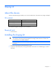
Rack options Ordering rack options HP provides several rack option kits to complement or complete your rack solution. The following table lists a sample of the available rack option kits. For information about ordering rack option kits, see the HP website (http://www.hp.com/go/rackandpower), or contact your nearest HP authorized reseller.
Baying kit About this device The HP V142 Rack Baying kit enables you to connect multiple racks of the same series, height, and depth. Kit contents Item Quantity 24-inch baying brackets 4 600-mm baying brackets 4 M5 self tapping screws 10 Extra hardware might be included for your convenience.
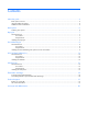
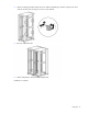
3. Attach two baying brackets (either 24-inch or 600-mm depending on the floor layout) to the front and rear of each rack set using two screws in each bracket. 4. Bay any additional racks. 5. Attach side panels to each end of the bayed racks. Installation is complete.
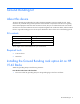
Ground Bonding kit About this device The HP V142 Rack Ground Bonding kit reduces the electromagnetic emissions outside the rack. These emissions are produced during normal operation of the electronic components within the rack. Typically, rack-mounted equipment must meet class A emissions levels, but you can reduce these levels even further.
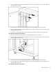
2. Place an M6 ground washer and an M6 ground nut over the grounding lug on the rack frame, and then tighten the ground nut. 3. Place the other end of the same grounding strap over the grounding lug on the front door. 4. Place an M6 ground washer and an M6 ground nut over the grounding lug on the front door, and then tighten the ground nut. 5. Repeat steps 1 through 4 to attach a grounding strap from the rear rack frame to the rear door. From the rear rack frame to the rack base 1.
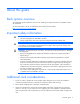
1. Place one end of the grounding strap over the grounding lug on the rear rack frame. 2. Place an M6 ground washer and an M6 ground nut over the grounding lug on the rack frame, and then tighten the ground nut. 3. Place the other end of the same grounding strap over the grounding lug on the top of the rack. 4. Place an M6 ground washer and an M6 ground nut over the grounding lug on the top of the rack, and then tighten the ground nut. 5.
Reference Item 3 M6 ground washer 4 Facility ground (not included with this kit) 5 M8 x 20 bolt From the rack frame to the top side panel, if installed: 1. Place one end of the grounding strap over the grounding lug on the rack frame. 2. Place an M6 ground washer and an M6 ground nut over the grounding lug on the rack frame, and then tighten the ground nut. 3. Place the other end of the same grounding strap over the grounding lug on the top side panel. 4.
2. Place an M6 ground washer and an M6 ground nut over the grounding lug on the rack frame, and then tighten the ground nut. 3. Place the other end of the same grounding strap over the grounding lug on the bottom side panel. 4. Place an M6 ground washer and an M6 ground nut over the grounding lug on the bottom side panel, and then tighten then ground nut. 5. Repeat steps 1 through 4 for the other bottom side panel.
HP V142 Rack Stabilizer kit About this device The HP V142 Rack Stabilizer kit provides stability and support and prevents possible tipping when you install, remove, or access equipment within the rack. Kit contents Item Quantity 600-mm (23.62-in) Front stabilizer assembly 1 M8 x 20-mm bolt 5 M8 flat washer 5 M8 lock washer 5 This kit might contain extra hardware for your convenience.
2. Insert and partially tighten four bolts with washers, securing the front foot to the front caster plate. 3. Tighten the bolts. Installation is complete.
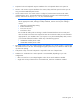
Side Panel kit About this device The HP V142 Rack Side Panel kit enables you to attach side panels to HP V142 Racks. Kit contents Item Quantity Top side panel 2 Bottom side panel 2 Key 2 This kit might contain extra hardware for your convenience. Required tools No tools are required for this procedure. Installing the side panels 1. Press the side panel latches and slide the bottom side panel into the rack.
2. Install the top side panel by locking the side panel lock, securing it to the rack. 3. Repeat steps 1 and 2 for the other side of the rack. Installation is complete.
Electrostatic discharge Preventing electrostatic discharge To prevent damaging the system, be aware of the precautions you need to follow when setting up the system or handling parts. A discharge of static electricity from a finger or other conductor may damage system boards or other static-sensitive devices. This type of damage may reduce the life expectancy of the device. To prevent electrostatic damage: • Avoid hand contact by transporting and storing products in static-safe containers.
Technical support Before you contact HP Be sure to have the following information available before you call HP: • Technical support registration number (if applicable) • Product serial number • Product model name and number • Product identification number • Applicable error messages • Add-on boards or hardware • Third-party hardware or software • Operating system type and revision level HP contact information For the name of the nearest HP authorized reseller: • See the Contact HP worldwi
Acronyms and abbreviations CPU central processing unit CRT cathode-ray tube KVM keyboard, video, and mouse PDU power distribution unit RKM rackmount keyboard monitor TMRA recommended ambient operating temperature UPS uninterruptible power system Acronyms and abbreviations 20