HP V142 Rack User Guide Part Number 597608-002 June 2010 (Second Edition)
© Copyright 2010 Hewlett-Packard Development Company, L.P. The information contained herein is subject to change without notice. The only warranties for HP products and services are set forth in the express warranty statements accompanying such products and services. Nothing herein should be construed as constituting an additional warranty. HP shall not be liable for technical or editorial errors or omissions contained herein.
Contents Before you begin .......................................................................................................................... 4 Optimum environment................................................................................................................................... 4 Space requirements ............................................................................................................................ 4 Power requirements ...........................................
Before you begin Optimum environment Specific requirements for space, power, temperature, and airflow must be met to provide optimum performance with minimum maintenance for your rack environment. For additional information, refer to the Best Practices document on the HP website (http://h18004.www1.hp.com/products/servers/proliantstorage/racks).
CAUTION: To reduce the risk of damage to the equipment when installing third-party options: • Do not permit optional equipment to impede airflow around the component or to increase the internal rack temperature beyond the maximum allowable limits. • Do not exceed the manufacturer’s TMRA. Airflow requirements HP rack-mountable products typically draw in cool air through the front and exhaust warm air out through the rear of the rack.
• Power—If a UPS is installed, do not exceed its output rating. Be sure to review the installation instructions provided with each component for important cautions and warnings. • PDUs—Before installing other components, install the PDUs. • Height—The height of the rack and of rack-mountable components is measured in U increments, where U = 4.5 cm (1.75 in).
WARNING: To reduce the risk of personal injury or damage to the equipment, be sure that: • The leveling feet are extended to the floor. • The full weight of the rack rests on the leveling feet. • The stabilizing feet are attached to the rack if it is a single-rack installation. • The racks are coupled together in multiple-rack installations. • Only one component is extended at a time. A rack may become unstable if more than one component is extended for any reason.
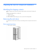
Preparing the rack for component installation Identifying the shipping contents Unpack the shipping carton and locate the materials and documentation CD necessary for setting up the rack. In addition to these supplied items, you might need: • Adjustable wrench • Options to be installed For comfort and efficiency while setting up your rack, use power tools where applicable.
2. Pull the top hinge pin down, and tilt the door away from the rack. 3. Lift the door up to remove it from the bottom hinge. Store the door in an upright position, taking care to protect it from damage. Removing the rear door 1. Unlock the door and open it.
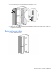
2. Open the hinge bracket by pulling down on the top hinge pin. 3. Lift the rear door off the hinge bracket and remove it from the rack. Store the doors in an upright position, taking care to protect them from damage.
Stabilizing the rack Stabilizing requirements Rack stability is important when equipment is routinely installed, removed, or accessed within the rack. To achieve stabilization, use an HP V142 Rack Stabilizer Option Kit or HP V142 Rack Baying Option Kit. Observe the following tips when using multiple-rack configurations: • A stabilizer kit is required or recommended, depending on your rack configuration. • The number of baying kits needed is one less than the total number of racks in a row.
Rack baying option kit You can bay racks together by installing the HP V142 Rack Baying Option Kit, as long as the racks are the same series, height, and depth. This configuration helps decrease space needs and increase stability. For more information, see the HP V142 Baying Rack Option Kit Installation Instructions.
Installing components Installing rack components IMPORTANT: These installation instructions are for standard installations. For specific installation instructions, refer to the documentation included with your component. The following steps outline the sequence for installing rack-mountable components in a rack. HP strongly recommends installing a stabilizer foot before any other component. Install 0U devices first, such as PDUs, console switches, and so on. To install components: 1.
Rack options Ordering rack options HP provides several rack option kits to complement or complete your rack solution. The following table lists a sample of the available rack option kits. For information about ordering rack option kits, see the HP website (http://www.hp.com/go/rackandpower), or contact your nearest HP authorized reseller.
Specifications HP V142 Rack specifications Item Specification U height 42U Width 600 mm (23.62 in) Depth 1,070 mm (42.13 in) Static load 907.
Electrostatic discharge Preventing electrostatic discharge To prevent damaging the system, be aware of the precautions you need to follow when setting up the system or handling parts. A discharge of static electricity from a finger or other conductor may damage system boards or other static-sensitive devices. This type of damage may reduce the life expectancy of the device. To prevent electrostatic damage: • Avoid hand contact by transporting and storing products in static-safe containers.
Technical support Before you contact HP Be sure to have the following information available before you call HP: • Technical support registration number (if applicable) • Product serial number • Product model name and number • Product identification number • Applicable error messages • Add-on boards or hardware • Third-party hardware or software • Operating system type and revision level HP contact information For the name of the nearest HP authorized reseller: • See the Contact HP worldwi
Acronyms and abbreviations CPU central processing unit CRT cathode-ray tube KVM keyboard, video, and mouse PDU power distribution unit RKM rackmount keyboard monitor TMRA recommended ambient operating temperature UPS uninterruptible power system Acronyms and abbreviations 18
Index A specifications 15 stabilizing your rack 11 additional rack considerations 5 E electrostatic discharge 16 F front door, removing 8 G general guidelines 6 grounding methods 16 I installing components 13 installing rack components 13 N notices 2 O optimum environment 4 ordering options 14 P preparing the rack for component installation 8 R rack baying option kit 12 rack doors, removing 8, 9 rack options 14 rack stabilizer option kit 11 rear doors, removing 9 removing the front door 8 removing