
ACC X.25 Data Analyzer User's Guide

Network Configuration
Setting Up the Network Configuration File
Appendix A 45
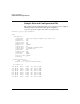
Port Definitions
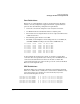
Each port on each multiplexer card to be used for the Data Analyzer
must be correctly configured to support the Frame capture firmware
protocol. Note the following configuration requirements:
• Select the correct mux and port for each analyzer connection.
• Set RS232 mode for both RS-232 and V.35 analyzer ports.
• The baud rate is not important but set for an expected nominal rate
(57600 chosen here).
• The Clocking option must be set to Ext.
• The Mode, clock multiplier, and encoding must be set to SDLC, x1,
and NRZ. If NRZI encoding is used set this to NRZI instead.
Port 00:00 RS232 57600 Int SDLC x1 NRZ
Port 00:01 RS232 57600 Ext SDLC x1 NRZ
Port 00:02 RS232 57600 Ext SDLC x1 NRZ
Port 00:03 RS232 57600 Ext SDLC x1 NRZ
Port 00:04 RS232 57600 Ext SDLC x1 NRZ
Port 00:05 RS232 57600 Ext SDLC x1 NRZ
Port 00:06 RS232 57600 Ext SDLC x1 NRZ
Port 00:07 RS232 57600 Ext SDLC x1 NRZ
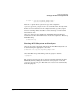
In the example file, mux 0 ports 0 and 1 are used for a sample X.25
connection that is looped back between these ports. marked External is
connected as described below. Connect the Y-cable as shown. The
connector designated “P2” on the Y-cable goes to the connector marked
External on the loopback cable.
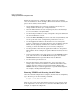
ZLU Definitions
Finally the ZLUs to be used for the Analyzer session must be defined.
Take care to define these carefully since errors in these definitions may
not be detected by ttgen. If there are such errors they may not be
detected until the ports are used.
Term 0019 0:2 HDLC.FRAME 0 0 90 20 1 0 0 ”Protocol Analyzer”
Term 0020 0:3 HDLC.FRAME 0 0 90 19 2 0 0 ”Protocol Analyzer”
Term 0021 0:4 HDLC.FRAME 0 0 90 22 1 0 0 ”Protocol Analyzer”
Term 0022 0:5 HDLC.FRAME 0 0 90 21 2 0 0 ”Protocol Analyzer”
Term 0023 0:6 HDLC.FRAME 0 0 90 24 1 0 0 ”Protocol Analyzer”
Term 0024 0:7 HDLC.FRAME 0 0 90 23 2 0 0 ”Protocol Analyzer”