
ACC X.25 Protocol User's Guide

ZX25D X.25 Protocol Driver
Configuration
Chapter 3 31
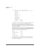
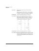
Z7340A 0 0:2:0 /opt/acc/z7340a/x25.zabs
Z7340A 1 0:5:0 /opt/acc/z7340a/x25.zabs
Z7340A 2 0:8:0 /opt/acc/z7340a/x25.zabs
The “.zabs” firmware file must have at least the X.25 and LAP-B protocol
modules loaded into it, and it may contain other protocol modules. Refer
to the TTGEN section of the ACC Utilities Reference Guide for more
information on specifying the Mux number, bus, and slot parameters.
Port Definitions
On 2-port or 8-port cards, the ports used for X.25 must be defined as
operating in SDLC mode. They will normally be defined with an external
(modem supplied) clock; however, especially for a DCE link terminal, an
internal (card supplied) clock may be used. With an external (modem
supplied) clock, the speed is for documentation purposes only, and will
not be used by the ZCOM subsystem.
The clock multiplier should be x1, and the encoding mode will normally
be NRZ.
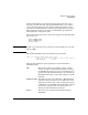
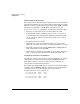
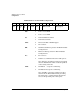
A sample z7340a port definition for X.25 is as follows:
Port 01:4 RS232 9600 Ext SDLC x1 NRZ
Refer to the TTGEN section of the ACC Utilities Reference Guide for
more information on specifying the port parameters.
X.25 Link Term Definitions
Each port or E1/T1 subchannel to be used for X.25 must have one (and
only one) X.25 link terminal defined. The link terminal defines the
parameters for the HDLC/LAP-B protocol (level 2 of X.25), as well as
defining some parameters related to the X.25 subscription, and global
default parameters for all virtual circuits on this port.
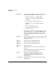
The X.25 link terminal is defined by a TERM definition entry. Physically,
the TERM definition for the link terminal must precede the virtual
circuit definitions for each port. A sample X.25 link terminal definition
line is as follows: