
ACC X.25 Protocol User's Guide

ZX25D X.25 Protocol Driver
Configuration
Chapter 338
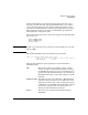
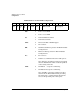
LCN Assignment Constraints
The Logical Channel Number (LCN) assignment table is used to indicate
which channel numbers to use for PVCs and the different types of SVCs.
The table is always specified from the perspective of the DTE, even if the
link has been configured as a DCE. When assigning the last_pvc,
first_insvc, last_insvc, etc. parameters, the following constraints apply:
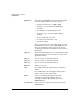
• The range of values that may be used for LCNs is 1 to 4095.
• The maximum number of LCNs that can be in use at one time on
each X.25 link is 254 on the Z7200A, Z7400A, and Z7350A interface
cards. On all other ACC cards, up to 1023 LCNs may be used on
each X.25 link.
• The PVC LCNs must start at 1.
• The LCN ranges that are assigned for PVCs, one-way incoming
SVCs, two-way SVCs, and one-way outgoing SVCs must not overlap.
• The LCN assignment table specified must agree exactly with the
LCN assignments used for the DXE.
• When defining your Virtual Circuit ZLUs, you must not define more
VCs of a given type than declared in the LCN assignment table.
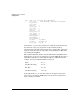
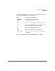
Configuration Parameters Definition
The following configuration values are currently defined for use in X.25
configuration as a replacement for the POLL and SELECT address
fields. These values are used as a symbolic way of configuring the
associated two 16-bit hexadecimal values.
For example, X25_LINK_DTE_400 can be used to set the POLL address
to 0x800a, and the SELECT address to 0x146a. If a particular desired
configuration value is not provided by these values, then two
hexadecimal values can be used instead.
X25_LINK_DTE_400 800Ah 146Ah
X25_LINK_DCE_400 000Ah 146Ah
X25_LINK_DTE_1600 800Ah 486Ah
X25_LINK_DCE_1600 000Ah 486Ah