
ACC X.25 Protocol User's Guide

ZX25D X.25 Protocol Driver
Virtual Circuit Definitions
Chapter 3 49
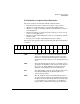
Udata "abc\\045def"
This will place the ASCII characters “abc\045def” into
the Udata buffer.
Note that the X25UDT Logical-Data area must be
defined before you can use the Udata parameter. Refer
to the “Reserved Logical Data Area Definition” section
on how to allocate this storage.
Note that call user data is always assumed to start
from byte 0 in its X25UDT Logical-Data area. Contrast
this with Ldata, which can be offset anywhere within
its Logical-Data area. Udata and Ldata areas in the
Logical-Data area must not overlap or go beyond the
end of the Logical-Data area. If you wish, you are
allowed to define the X25UDT Logical-Data area to be
bigger than is needed for Udata and place Ldata
entries in the remaining space in the Logical-Data area
after the Udata area.
Udata and Ldata are associated with the Term or
Lterm entry previously defined before them. Term and
Lterm entries have application numbers associated
with them. Udata and Ldata reside in a Logical-Data
area that has an application number associated with it.
The application number of this Logical-Data area and
the Term or Lterm entry must match, or the application
number of the Logical-Data area must be zero (0). Else
an error will be reported.
(Note that instead of using the Udata parameter, the
user could specify call user data using the Ldata
parameter. However, the user would have to specify
some things explicitly using the Ldata parameter
whereas the Udata parameter simplifies this process
by automatically determining some of these things. For
example, which Logical-Data area to use, the size of the
data. In particular, Udata allows the user to more
easily intermix ASCII characters and non-ASCII bytes
in the same buffer. This could be done with multiple
Ldata parameters, but it would require painstaking
attention to detail to make sure the offsets and buffer
locations were correct.)