
ACC X.25/ISDN Data Analyzer User's Guide


52 AppendixA
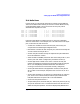
Analyzer Cable Assemblies
V.35 Cable Assembly
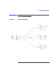
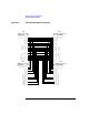
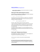
Figure A-4 V.35 Cable Assembly (Continued)
P1
(Male Connector)
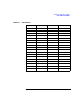
Signal name ID
Chassis Gnd A
Signal Gnd B
RTS C
CTS D
DSR E
RLS F
DTR H
TXD(A) P
TXD(B) S
RXD(A) R
RXD(B) T
TT(A) U
TT(B) W
RXC(A) V
RXC(B) X
TXC(A) Y
TXC(B)AA
P2
(Female Connector)
ID Signal Name
A Chassis Gnd
B Signal Gnd
C RTS
D CTS
E DSR
F RLS
H DTR
P TXD (A)
S TXD (B)
R RXD (A)
T RXD (B)
P4
(Male Connector)
ID Signal Name
A Chassis Gnd
B Signal Gnd
C RTS
D CTS
E DSR
F RLS
H DTR
P TXD(A)
S TXD(B)
R RXD(A)
T RXD(B)
U TT(A)
W TT(B)
V RXC(A)
X RXC(B)
Y TXC(A)
AA TXC(B)
Chassis Gnd A
Signal Gnd B
RTS C
CTS D
DSR E
RLS F
DTR H
TXD (A) P
TXD (B) S
RXD (A) R
RXD (B) T
TT (A) U
TT (B) W
RXC (A) V
RXC (B) X
TXC (A) Y
TXC (B) AA
P3
(Male Connector)
Signal name ID
UTT(A)U
WTT(B)W
V RXC (A)
X RXC (B)
Y TXC (A)
AA TXC (B