
ACC X.25/ISDN Data Analyzer User's Guide


Appendix B 57
Network Configuration
Setting Up the Network Configuration File
Port Definitions
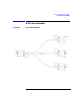
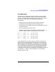
Each port on each multiplexer card to be used for the D ata Analyzer
must be correctly configured to support the Frame capture firmware
protocol. In the 8-channel sample shown below, ports 2 to 7 on mux 0
are used for analyzer ports. Note the following configuration
requirements:
• Select the correct mux and port for each analyzer connection.
• Set RS232 mode for both RS-232 and V.35 analyzer ports.
• The baud rate is not important but set for an expected nominal rate
(57600 chosen here).
• The Clocking option must be set to Ext.
• The Mode, clock multiplier, and encoding must be set to SDLC, x1,
andNRZ.IfNRZIencodingisusedsetthistoNRZIinstead.
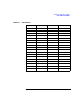
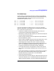
Port 00:00 RS232 57600 Int SDLC x1 NRZ
Port 00:01 RS232 57600 Ext SDLC x1 NRZ
Port 00:02 RS232 57600 Ext SDLC x1 NRZ
Port 00:03 RS232 57600 Ext SDLC x1 NRZ
Port 00:04 RS232 57600 Ext SDLC x1 NRZ
Port 00:05 RS232 57600 Ext SDLC x1 NRZ
Port 00:06 RS232 57600 Ext SDLC x1 NRZ
Port 00:07 RS232 57600 Ext SDLC x1 NRZ
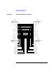
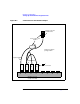
Intheexamplefile,mux0ports0and1areusedforasampleX.25
connection that is looped back between these ports. Use the loopback
cable supplied with the selected ACC interface panel to connect these
ports (see Figure B-1). Ensure the end marked Internal is connected to
port0,andtheendmarkedExternal is connected as described below.
Connect the Y-cable as shown. The connector designated “P2” on the
Y-cable g oes to the connector marked External on the loopback cable. See
also Appendix A , “Analyzer Cable Assemblies,” for more detailed
description of the Y-cable.