
Installation and Reference Guide HP AdvanceStack 100Base-THub-12TX, Hub-12TXM, and Switch Modules 1997-06

HP Hub-12TX/Hub12-TXM Installation and Reference Guide
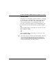
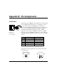
B-2 Pin Assignments
DB9 Serial Port Pin Description
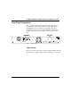
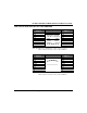
Figure B.2
DB9 Serial Port
(on the Hub Side)
The DB9 serial port on the front panel is used to connect the
hub to a management device. The VT-100 console interface
can be accessed from a terminal, a PC running a terminal
emulation program, or from a remote location via a modem
connection. Network management software (which provides a
graphical interface) can also be used to discover and map the
hub from a remote location via a modem connection, running
SLIP over TCP/IP. You can use the serial port to configure
port settings (e.g., enabled or disabled), or to update device
firmware. The pin assignments used to connect various device
types to the hub’s Console Port are provided in the following
tables.
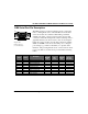
EIA
Circuit
CCITT
Signal
Description
Hub’s
DB9 DTE
Pin #
PC DB9
DTE
Pin #
Modem
DB25 DCE
Pin #
Signal
Direction
DTE -DCE
CF 109 DCD (Data Carrier Detected) 1 1 8 < --------
BB 104 RxD (Received Data) 2 2 3 < --------
BA 103 TxD (Transmitted Data) 3 3 2 -------- >
CD 108.2 DTR (Data Terminal Ready) 4 4 20 -------- >
AB 102 SG (Signal Ground) 5 5 7 ----------
CC 107 DSR (Data Set Ready) 6 6 6 < --------
CA 105 RTS (Request-to-Send) 7 7 4 -------- >
CB 106 CTS (Clear-to-Send) 8 8 5 < --------
CE 125 RI (Ring Indicator) 9 9 22 < --------
Table B.2 DB9 Port Pin Assignments