HP AdvanceStack Switch 100Base-T Module Installation Guide
© Copyright 1996 Hewlett-Packard Company All Rights Reserved Reproduction, adaptation, or translation without prior written permission is prohibited, except as allowed under the copyright laws.
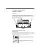
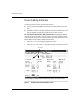
HP AdvanceStack Switch 100Base-T Module At A Glance The HP AdvanceStack Switch 100Base-T Module (HP J3191A) is an optional component that you can add to an HP AdvanceStack Switch 2000. The 100Base-T module has two slots into which you can install your choice of available HP 100Base-T transceivers.
HP AdvanceStack Switch 100Base-T Module ■ You can exchange, or remove either the module itself or a transceiver in the module. (Note that transceivers are to be installed in a module that is removed from the Switch 2000.) ■ Because the 100Base-T Module is a “low power” module, you can install up to six 100Base-T Modules in your Switch 2000, enabling you to “fully load” the switch with up to 12 ports.
HP Customer Support Services How to get the latest software/agent firmware You can download a compressed file (j3100a.exe) containing the latest version of the HP Switch 2000 software, proprietary MIB, and a software download utility file (update.exe). from the HP BBS, HP FTP Library Service, CompuServe, and the World Wide Web. After you download the file, extract the file by typing: filename /x. For example, j3100a.exe /x.
HP FIRST Fax Retrieval Service HP FIRST is an automated fax retrieval service that is available 24 hours a day, seven days a week. HP FIRST provides information on the following topics: ■ Product information ■ Troubleshooting instructions ■ Technical reviews and articles ■ Configuration information To access HP FIRST, dial one of the following phone numbers: Location Phone Number U.S. and Canada Only Dial 1 (800) 333-1917 with your fax machine or touch-tone phone and press 1. Outside the U.S.
Contents At A Glance . . . . . . . . . . . . . . . . . . . . . . . . . . . . . . . . . . . . . . . . . . . . . . . . . . . . iii Installation . . . . . . . . . . . . . . . . . . . . . . . . . . . . . . . . . . . . . . . . . . . . . . . . . . . . 1 Included Parts . . . . . . . . . . . . . . . . . . . . . . . . . . . . . . . . . . . . . . . . . . . . . . . 1 Downloading Software . . . . . . . . . . . . . . . . . . . . . . . . . . . . . . . . . . . . . . . . . . Software Sources and Content . . . . . . . . . .
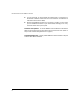
Installation Installation You can install a 100Base-T Module into any of the Switch 2000’s six module slots. The following steps provide an overview. The actual installation procedure begins on page 2. 1. Determine whether your Switch 2000 is running the necessary operating system (OS) version and, if necessary, download a new version (page 2). 2. Install one or two 100Base-T transceivers into the 100Base-T module (page 6). 3. Install the 100Base-T Module in a Switch 2000 slot (page 7). 4.
Downloading Software Downloading Software Use this procedure in either of the following cases: ■ You are installing a 100Base-T Module in your Switch 2000 for the first time. ■ A 100Base-T Module is already installed in the Switch 2000 and you now want to upgrade the operating system (OS) to a newer version. Do You Need To Download a New OS Version? The 100Base-T Module requires OS version A.02.50 or later to operate in the Switch 2000.
Downloading Software 3. Check the “OS Version” line in the Switch Information screen. • If the version number is A.02.50 or later, the Switch 2000 can support the 100Base-T Module. In this case, go to “Installing the 100Base-T Module in an Unused Slot” on page 7. • If the version number is earlier than A.02.50, download a new OS before installing the 100Base-T Module. In this case, continue with the instructions in this section before you install the module.
Downloading Software Observe the following when downloading the OS software to the Switch 2000: – filename.swi and filename.fdd must be in the same directory. – filename must be the same for both files (that is, the files must be the .swi and .fdd file pair from the disk or from the selfextracting j3100a.exe file. For the above reasons, do not place the filename.swi and filename.fdd in separate directories, and do not rename them.
Downloading Software 2. Download the software upgrade by using one of the following methods: • TFTP download using a TFTP server and the Download OS option in the Switch 2000 console interface: This is the recommended download method if you have TFTP server access to the Switch 2000. Refer to the instructions in appendix A, “Downloading an Operating System”, in the Console User’s Guide you received with your Switch 2000. For this option, use the form filename.swi for the Remote File Name parameter.
Adding, Replacing, or Removing a Transceiver For more information on the Download OS feature, refer to appendix A, “Downloading an Operating System” in the Console User’s Guide you received with your Switch 2000. Adding, Replacing, or Removing a Transceiver Caution When adding, removing, or replacing a transceiver from a HP 100Base-T Switch Module, always remove the module from the Switch 2000 first. While the modules are hot swappable, the transceivers are not.
Installing the 100Base-T Module in an Unused Slot Installing the 100Base-T Module in an Unused Slot Caution Static electricity can severely damage the sensitive electronic components on the HP AdvanceStack Switch 100Base-T Module. When handling and installing the module in your switch, follow these procedures to avoid damage from static electricity: ■ Handle the module by its edges and avoid touching the components and the circuitry on the board.
Installing the 100Base-T Module in an Unused Slot 2. The LED label strips have a small loop on the left end. Use your fingernail or a small implement to catch the loop and slide the label to the left and out of the label slot. Then insert the LED label strip you received with the 100Base-T Module. For example, if you are going to install the module in slot “A”, you would replace the blank LED label strip in label slot “A” with the new LED label strip for the 100Base-T Module.
Installing the 100Base-T Module in an Unused Slot 6. Seat the module in the slot by simultaneously pushing up on both extractor handles until they are firmly seated against the front panel of the module (in the closed position). You should be able to see the module pull into the slot when you raise the handles. Extractor Handles in the “Closed” Position Figure 4.
Installing the 100Base-T Module in an Unused Slot Slot and Port LED Behavior LED Pattern Slot Fault (for the slot in which you are installing the module) 1. FLASHING RAPIDLY if the module is not properly installed 2. ON for less than 1 second after the module has been properly installed. 3. OFF during normal switching operation. 4. FLASHING SLOWLY if there is a self-test failure. Check the switch event log through the console interface for more information. 5.
Installing the 100Base-T Module in an Unused Slot Tighten These Two Screws Figure 6. 8. Securing the Module in the Slot Connect the appropriate network cables to the module’s 100Base-T ports. See the transceiver manual for a description of the supported cable type. Category 5 cable. Maximum: 100 meters Hub to hub: crossover cable Switch to switch: crossover Switch to end node: straight-through Figure 7. Fiber-optic cable. The maximum distance depends on the device connected to this port.
Installing the 100Base-T Module in an Unused Slot 9. Check the port LEDs for the newly-installed module to ensure that the port(s) connected in the preceding step are operating correctly. (If you have not already done so, install the LED label strip as described in step 1 on page 7.) The “port-enabled” LED (1, 2) will be lit for each port that is operating correctly.
Installing the 100Base-T Module in an Unused Slot Rebooting the Switch You can reboot the switch either by using the Reboot Switch command in the console Main menu or by pressing the recessed Reset button located to the right of the Power LED. Reset Button Figure 9. Location of the Reset Button Generally, you only need to reboot the switch when it needs to recognize a change in its hardware or software (console) configuration.
Removing or Replacing a Module Removing or Replacing a Module Use this section to do either of the following: ■ Replace one module with another ■ Remove a module without replacing it Loosen These Two Screws Figure 10. Note 1. Remove any network cables from the ports on the module. 2. Loosen the screws in the extractor handles of the module you want to remove from the switch. (Refer to figure 10, above.) 3.
Removing or Replacing a Module 5. Do one of the following: • If you will be installing another 100Base-T module in the slot, go to “Installing the 100Base-T Module in an Unused Slot” on page 8 and begin with step 3. To install another module type, refer to the manual you received with that module. Make sure that you install the proper LED strip for the new module you are installing, as described in step 1 on page 7.
Troubleshooting Troubleshooting The primary tools for troubleshooting the 100Base-T Module are the LEDs on the front of the Switch 2000. Refer to “Slot and Port LED Behavior” on page 10. Also, refer to the installation guide shipped with the Switch 2000 for more detailed troubleshooting information.
Specifications Specifications Physical Dimensions Width: Depth: Height: Weight: 16.5 cm (6.5 in) 25.0 cm (9.8 in) 4.3 cm (1.7 in) 0.72 lbs (0.33 kilos) Environmental Operating temperature: 0°C to 55°C (32°F to 131°) Relative humidity: 15% to 95% at 40°C (104°F) non-condensing Maximum altitude: 4.6 km (15,000 feet) Connectors The 100Base-T Module ports are compatible with the IEEE 802.3u standard, and are designed to accept 100Base-T transceivers (such as 100Base-TX and 100Base-FX) only.
Regulatory Statements Regulatory Statements FCC Statement (U.S.A.) This equipment has been tested and found to comply with the limits for a Class A digital device, pursuant to Part 15 of the FCC Rules. These limits are designed to provide reasonable protection against harmful interference when the equipment is operated in a commercial environment.
Regulatory Statements European Community This equipment complies with CISPR22/EN55022 Class A. Note This is a class A product. In a domestic environment this product may cause radio interference in which case the user may be required to take adequate measures. Declaration of Conformity This product is designed for operation with the Switch 2000 and is listed in the Declaration of Conformity available from your HP-authorized dealer or reseller and the Switch 2000 installation manual.