
Installation and Reference Guide HP AdvanceStack 100Base-THub-12TX, Hub-12TXM, and Switch Modules 1997-06

HP Hub-12TX/Hub-12TXM Installation and Reference Guide
Hardware Reference 5-9
Diagnostic Test Indicators
After power on, the hub automatically performs a diagnostic
test of hardware components. The diagnostic tests display
results for the Hub-12TX/Hub-12TXM repeater board via the
Partition/Disable LEDs on the front panel. Test results for the Hub-
12TXM management agent can only be seen via the VT-100
console interface. The following table shows how test results
for the repeater board are indicated by the
Partition/Disable LEDs.
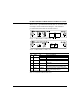
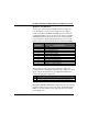
Partition/Disabled
Test Function/Component
LED Indicator of Hub Repeater Board
1
Boot ROM
2
Hub Configuration EEPROM
3
RAM for Repeater Board CPU
4
Repeater Information Base SRAM
5
Repeater Interface Controller
7
Routing Table for Internal Exp Port
8
Input Queue for Internal Exp Port
9
Output Queue for Internal Exp Port
10
Routing Table for External Exp Port
11
Input Queue for External Exp Port
12
Output Queue for External Exp Port
Table 5.12 Diagnostic Results
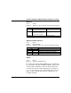
The system tests each component one at a time. The corres-
ponding indicator will light up (ON) after test completion to show
which component failed the test. No light means all the hub
components passed the diagnostics.
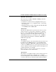
State Indication
ON Corresponding hardware component failed the diagnostic test.
OFF Corresponding hardware component successfully passed the diagnostic test.
Table 5.13 Diagnostic Indicators
The Hub-12TX/Hub-12TXM will complete the test cycle even if a
problem is detected on any of the components. If all
Partition/Disable
LEDs are off, then all the tested components have successfully
passed diagnostics.