HP Apollo a6000 Chassis Setup and Installation Guide Abstract This document contains setup, installation, and configuration information for the HP Apollo a6000 Chassis. This document is for the person who installs, administers, and troubleshoots the system. HP assumes you are qualified in the servicing of computer equipment and trained in recognizing hazards in products with hazardous energy levels.
© Copyright 2014 Hewlett-Packard Development Company, L.P. The information contained herein is subject to change without notice. The only warranties for HP products and services are set forth in the express warranty statements accompanying such products and services. Nothing herein should be construed as constituting an additional warranty. HP shall not be liable for technical or editorial errors or omissions contained herein. Microsoft® and Windows® are U.S. registered trademarks of Microsoft Corporation.
Contents Planning the installation ................................................................................................................. 5 Safety and regulatory compliance .................................................................................................................. 5 Site requirements .......................................................................................................................................... 5 Configuration guidelines ...........................
Configuring the system ................................................................................................................ 33 Power capping .......................................................................................................................................... 33 Power capping modes ...................................................................................................................... 33 Configuring a power cap ...................................................
Planning the installation Safety and regulatory compliance For safety, environmental, and regulatory information, see Safety and Compliance Information for Server, Storage, Power, Networking, and Rack Products, available at the HP website (http://www.hp.com/support/Safety-Compliance-EnterpriseProducts). Site requirements Select an installation site that meets the detailed installation site requirements described in the site planning guide on the Documentation CD and on the HP website (http://www.hp.com).
To install, configure, and access HP APM, see the HP Advanced Power Manager User Guide on the HP website (http://www.hp.com/support/APM_UG_en). Hot-plug power supply calculations For more information on the hot-plug power supply and calculators to determine server power consumption in various system configurations, see the HP Power Advisor website (http://www.hp.com/go/hppoweradvisor). Compiling the documentation The documentation, while delivered individually and in various formats, works as a system.
WARNING: Be sure to install chassis starting from the bottom of the rack and work your way up the rack. WARNING: To reduce the risk of personal injury from hot surfaces, allow the drives and the internal system components to cool before touching them. WARNING: To reduce the risk of electric shock or damage to the equipment: • Never reach inside the chassis while the system is powered up. • Perform service on system components only as instructed in the user documentation.
CAUTION: If a third-party rack is used, observe the following additional requirements to ensure adequate airflow and to prevent damage to the equipment: • Front and rear doors—If the 42U rack includes closing front and rear doors, you must allow 5,350 sq cm (830 sq in) of holes evenly distributed from top to bottom to permit adequate airflow (equivalent to the required 64 percent open area for ventilation).
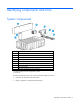
Identifying components and LEDs System components Item Description 1 HP Apollo a6000 5U Chassis 2 Server tray blank 3 Server tray* 4 Fan assembly (5) 5 I/O module 6 Power cage (Right) 7 Management module 8 Power cage (Left) 9 HP Apollo a6000 5U Chassis 5U Rail kit** * The quantity depends on the configuration ordered.
Server tray bay numbering Rear panel components Item Description 1 I/O modules (10) 2 Fan assemblies (5) 3 Power cage (Right) 4 Management module 5 Power cage (Left) Identifying components and LEDs 10
Fan assembly bay numbering The chassis has five fan assemblies located in the rear of the chassis. The following figure identifies the fan assemblies by device number. Fan LED Status Description Off The fan is working or the power is off. Solid amber The fan has failed.
Management module components Item Description Label 1 Management connector MGMT 2 Reserved SLAPM1 3 HP APM connector SLAPM2 4 Network 1 connector — 5 Network 2 connector — IMPORTANT: Do not connect both iLO ports to the network at the same time. Only one iLO port can be connected to the network, while the other iLO port can be used only as a connection to a second enclosure. Having both ports connected at the same time results in a loopback condition.
Item Description 1 UID LED 2 Network 1 link LED 3 Network 1 activity LED 4 Network 2 link LED 5 Network 2 activity LED I/O module bay numbering The chassis has ten I/O module bays located in the rear of the chassis. Power shelf rear panel components NOTE: The single-phase power shelf is shown below. A three-phase power shelf is also available.
Power supply LEDs Power LED 1 (green) Fault LED 2 (amber) Condition Off Off No AC power to the power supply On Off Normal Off On Power supply failure Identifying components and LEDs 14
Installing the chassis Installation overview To set up and install the chassis: 1. Unpack the system ("Unpacking the system" on page 15). 2. Determine the chassis rack spacing ("Determining the chassis rack spacing" on page 15). 3. Install the rack rails ("Installing the rack rails" on page 15). 4. Install the chassis in the rack ("Installing the chassis in the rack" on page 15). 5. Install the system components ("Installing the system components" on page 17). 6.
WARNING: The chassis is very heavy. To reduce the risk of personal injury or damage to the equipment, do the following: • Observe local occupational health and safety requirements and guidelines for manual material handling. • Get help to lift and stabilize the product during installation or removal, especially when the product is not fastened to the rails. The chassis weighs more than 25.85 kg (57.00 lb), so at least four people must lift the chassis into the rack together.
1. Install the chassis into the rack. 2. Secure the chassis to the rack. Installing the system components If components were removed during the chassis installation or additional components were ordered, install each device using the procedures in this section. If you perform any of the procedures in this section after powering on the chassis, ensure proper airflow by ensuring that each bay inside the chassis and at the rear of the chassis is populated with either a component or a blank.
CAUTION: To prevent improper cooling and thermal damage, do not operate the chassis unless all bays are populated with a component or a blank. Install the component as indicated. Installing a server CAUTION: To prevent improper cooling and thermal damage, do not operate the chassis unless all bays are populated with a component or a blank. To install the component: 1. Prepare the server for installation.
2. Install the server. When seated properly, the server will be flush with the front of the chassis and the release lever will close completely without resistance. Installing an I/O module Install the component as indicated.
Installing the fans Install the component as indicated. Installing a power cage CAUTION: To prevent damage to the component, power down the chassis and disconnect all power cords before removing or installing the component. To install the component: 1. Remove the power cage cover.
2. Install the power cables in the power cage. 3. Install the power cage cover. 4. Install the power cage. a. Insert the power cage into the correct power cage bay. b. Close the release lever.
c. Tighten the screw to secure the power cage to the chassis. Installing the management module IMPORTANT: Always complete the installation of both power cages before installing the management module. Install the component as indicated. Installing the power shelf CAUTION: To prevent damage to the component, power down the chassis and disconnect all power cords before removing or installing the component.
1. Install the power shelf rack rails into the rack. For more information, see the HP Apollo 6000 Power Shelf Rack Rail in HP Racks Installation Instructions. 2. Install the power shelf. 3. Secure the power shelf to the rack.
4. Install the power supplies into the power shelf, if needed. NOTE: If additional clearance is required to install power cables, loosen the thumb screw on either side of the shelf and slide the shelf out while installing the cables. Use caution to avoid bending the shelf. 5. Remove the power supply vent cover. 6. Install the 12V DC power cables. a. Insert the cable through the wide opening on either end of the power shelf, and then connect it to the appropriate connector.
b. Slide the cables toward the center, allowing them to straighten and hang from the rear of the power shelf. 7. Install the cable guard. NOTE: Cables are removed for clarity.
8. Install the power supply vent cover to protect the power supply vents.
Cabling Cabling overview WARNING: Be sure that all circuit breakers are locked in the off position before connecting any power components. CAUTION: To avoid damaging the fiber cables, do not drape cables from one side of the rack to the other and do not run cables over a hard corner or edge. CAUTION: To avoid damaging the cable, squeeze the thermal boot on the cable before disconnecting from the connector. After the hardware is installed, complete the following cabling procedures: 1.
• Connecting three chassis to one power shelf Cabling 28
• Connecting four chassis to one power shelf Cabling 29
• Connecting six chassis to one power shelf Cable quantity and length are determined by the configuration of components. For more information, see the HP Power Advisor (http://www.hp.com/go/hppoweradvisor). Example configurations Configuration examples can be calculated using the HP Power Advisor Tool (http://www.hp.com/go/hppoweradvisor). This tool is designed for facilities planning purposes only. Values obtained from the tool are based on worst case loads.
Connecting the optional HP APM module 1. Connect the HP APM to the network (green cables). 2. Connect the HP APM to the chassis (red cables). 3. Connect the HP APM to the power shelf (blue cable).
Connecting power cables and applying power to the chassis 1. Connect the DC power cable to the power shelf. 2. Connect the AC power cables to the power source (UPS or wall outlet) or to an installed PDU.
Configuring the system Power capping The HP ProLiant XL family of products provides a power capping feature that operates at the server enclosure level. The capping feature can be activated with PPIC.EXE, a stand-alone utility that runs in the environment of one of the resident servers in the chassis to be power capped. After a power cap is set for the enclosure, all the resident servers in the enclosure will have the same uniform power cap applied to them until the cap is either modified or canceled.
PPIC is a standalone utility that runs on a single server within the enclosure. For more information, see the HP ProLiant Power Interface Control (PPIC) Utility User Guide on the HP website (http://www.hp.com/support/PPIC_UG_en). • HP Advanced Power Manager HP APM is a rack level device that can control power caps for all enclosures in the rack. For more information, see the HP Advanced Power Manager User Guide on the HP website (http://www.hp.com/support/APM_UG_en).
If NONE is specified instead of a cap wattage value, then HP APM removes all (or the specified zone) of the power caps. To remove baseline data from the EEPROM and to remove the power cap setting, enter the following command: >SET POWER BASELINE NONE After this command is issued, the only way to re-establish a power baseline is to issue the SET POWER BASELINE command. The system returns to the default power cap mode (mode 1).
Troubleshooting Troubleshooting resources The HP ProLiant Gen8 Troubleshooting Guide, Volume I: Troubleshooting provides procedures for resolving common problems and comprehensive courses of action for fault isolation and identification, issue resolution, and software maintenance on ProLiant servers and server blades. To view the guide, select a language: • English (http://www.hp.com/support/ProLiant_TSG_v1_en) • French (http://www.hp.com/support/ProLiant_TSG_v1_fr) • Spanish (http://www.hp.
Electrostatic discharge Preventing electrostatic discharge To prevent damaging the system, be aware of the precautions you need to follow when setting up the system or handling parts. A discharge of static electricity from a finger or other conductor may damage system boards or other static-sensitive devices. This type of damage may reduce the life expectancy of the device. To prevent electrostatic damage: • Avoid hand contact by transporting and storing products in static-safe containers.
Regulatory information Safety and regulatory compliance For safety, environmental, and regulatory information, see Safety and Compliance Information for Server, Storage, Power, Networking, and Rack Products, available at the HP website (http://www.hp.com/support/Safety-Compliance-EnterpriseProducts). Turkey RoHS material content declaration Ukraine RoHS material content declaration Warranty information HP ProLiant and X86 Servers and Options (http://www.hp.
• Ensure that all cable connector screws are firmly tightened. • Use only HP supported peripheral devices. • Before system operation, ensure that all panels and cover plates are in place and secure.
Specifications Chassis environmental specifications Specification Value Temperature range* — Operating 10°C to 35°C (50°F to 95°F) Non-operating -30°C to 60°C (-22°F to 140°F) Maximum Wet bulb temperature — Operating 28ºC (82.4ºF) Non-operating 38.7ºC (101.7ºF) Relative humidity (non-condensing)** — Operating 10% to 90% Non-operating 5% to 95% * All temperature ratings shown are for sea level. An altitude derating of 1°C per 304.8 m (1.8°F per 1000 ft) to 3048 m (10,000 ft) is applicable.
Power specifications The power requirements for the HP Apollo a6000 5U Chassis are met by the following components: • HP 2450W Platinum Hot Plug Redundant Power Supply • HP 2650W Platinum Hot Plug Redundant Power Supply • HP Apollo 6000 Power Shelf • AC Input Module • Power Management Module DC power Specification Value Output 12V from power supplies to system chassis Minimum (V) +11.907 Nom (V) +12.25 Maximum (V) +12.593 % Reg +2.8%/-2.
Specification HP 2450W Platinum Hot Plug Redundant Power Supply HP 2650W Platinum Hot Plug Redundant Power Supply Rated input voltage 200 VAC to 208 VAC line to line 3-phase delta 200 VAC to 208 VAC line to line 3-phase delta Rated input frequency 50 Hz to 60 Hz 50 Hz to 60 Hz Maximum input current per line cord 22.
Support and other resources Before you contact HP Be sure to have the following information available before you call HP: • Active Health System log (HP ProLiant Gen8 or later products) Download and have available an Active Health System log for 3 days before the failure was detected. For more information, see the HP iLO 4 User Guide or HP Intelligent Provisioning User Guide on the HP website (http://www.hp.com/go/ilo/docs).
Acronyms and abbreviations EEPROM electrical erasable programmable read only memory ESD electrostatic discharge HP APM HP Advanced Power Manager iLO Integrated Lights-Out PDU power distribution unit PPIC HP ProLiant Power Interface Control Utility TMRA recommended ambient operating temperature UID unit identification UPS uninterruptible power system Acronyms and abbreviations 44
Documentation feedback HP is committed to providing documentation that meets your needs. To help us improve the documentation, send any errors, suggestions, or comments to Documentation Feedback (mailto:docsfeedback@hp.com). Include the document title and part number, version number, or the URL when submitting your feedback.
Index A airflow requirements 7, 8 authorized reseller 43 B battery replacement notice 5 battery warranty 38 bay numbering, fan 11 bay numbering, server tray 10 before you contact HP 43 BSMI notice 5 C cables 27 cables, networking 27 cabling 27 cabling, server 27 cabling, SL-APM module 31 chassis environmental specifications 40 chassis specifications 40 chassis, install in rack 15 compiling the documentation 6 compliance 5 components 9, 13 components, identification 9, 11, 13 components, system 9 configura
I installation overview 5, 15 installation, chassis 15 installation, fans 20 installation, rack rails 15 installing the chassis 15 installing the rack rails 15 internal cables 27 J Japanese notice 5 L LED identification 9 LEDs, fan 11 LEDs, management module 12 LEDs, troubleshooting 36 limited warranty 38 load protection guarantee 38 M management module 12, 22 management module components 12 management module LEDs 12 management module, installing 22 modifications, FCC notice 5 O optional components 17 o
T Taiwan battery recycling notice 5 technical support 43 telephone numbers 43 temperature requirements 8 TMRA (recommended ambient operating temperature) 8 troubleshooting 36 troubleshooting resources 36 troubleshooting, firmware upgrade utility 36 Turkey RoHS material content declaration 38 U Ukraine RoHS material content declaration 38 uninterruptible power supply (UPS) 5 unpacking the components 15 UPS (uninterruptible power supply) 5 W warnings 6 warranty 38 warranty information 38 website, HP 43 weig