Part V Storage security, best practices, and support information The following chapters describe storage security and SAN best practices: • “Storage security” (page 369) • “Best practices” (page 383) • “Support and other resources” (page 405)
1 Storage security This chapter describes storage security best practices.
Table 191 Security attack classes (continued) Attack class Description • Use data for fraudulent purposes • Deny authorized users access Nonmalicious attacks can result from: • Carelessness • Lack of knowledge • Circumventing security for nonmalicious purposes to perform tasks Attacks due to modifications to hardware or software made at the factory or during distribution. Distribution attacks can insert malicious code in a product, which can allow future unauthorized access to the system.
5. To ensure the validity of the peer, the server sends challenge messages at random intervals and changes the CHAP identifiers frequently. IPsec IPsec uses an open-standards framework to protect data transmission over IP networks. It uses cryptographic security services.
Advanced Encryption Standard AES is a block cipher designed for use in symmetric cryptography, which encrypts data in 128-bit blocks. AES can use a key size of 128, 192, or 256 bits. The number of rounds varies by the key length (for example, 10, 12, or 14 rounds for key sizes 128, 192, or 256, respectively). The processing in each round is more efficient than DES and is better suited to high-speed parallel operations.
the use of dial-in modems). Access control is a set of controls: confidentiality, integrity, availability, and limiting access to network resources. These depend on the successful prevention of unauthorized access to services or information.
Nonrepudiation Nonrepudiation ensures that all parties in a transaction are authenticated and verifies that they participated in the transaction. Storage technologies are tied closely with data and are often the last line of defense against attacks. Security validation Security validation establishes a secure audit trail across your organization. The audit trail serves as proof of compliance for internal and external audits with real-time alerts.
• Storage network—Consists of switches, appliances, and cables. Switches and appliances come with support to protect themselves. The storage network components support key management, encryption services, and authentication of server and storage arrays. • Servers—Consists of hardware, operating systems, interface cards (NICs and HBAs), and applications (also known as hosts). Each component comes with support for protecting itself. The interfaces cards support authentication and secure tunnel.
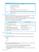
Hardware requirements SME requires a minimum of one MDS 9222i switch or one MSM-18/4 module in each cluster. The SME engines on the switch or module provide transparent encryption and compression to hosts and storage devices. A smart card reader is required to take advantage of all of the standard and advanced security levels. Software requirements Table 193 (page 376) lists the software requirements for switches and modules in the SME cluster.
Port security C-series port security features prevent unauthorized access to a switch port by: • Rejecting login requests from unauthorized Fibre Channel devices or switches • Reporting all intrusion attempts to the SAN administrator through system messages • Using the CFS infrastructure for configuration, distribution, and restricting it to CFS-enabled switches Fabric binding C-series switches in a fabric binding configuration ensure that ISLs are enabled between authorized switches only.
• Integration with HP Secure Key Manager, providing secure and automated key sharing between multiple sites to ensure transparent access to encrypted data • Industry-standard AES 256-bit encryption algorithms for disk arrays on a single security platform for SAN environments • Frame Redirection technology that enables easy, nonintrusive deployment of fabric-based security services • Plug-in encryption services available to all heterogeneous servers, including virtual machines, in data center fabrics
Fabric OS uses RBAC to determine which commands are supported for each user. Secure Shell Fabric OS supports SSH encrypted sessions to ensure security. SSH encrypts all messages, including client transmission of passwords during login. SSH includes a daemon (sshd), which runs on the switch and supports many encryption algorithms, such as Blowfish-CBC and AES. Commands that require a secure login channel must be issued from an original SSH session.
IPFilter policy The B-series IPFilter policy applies a set of rules to IP management interfaces as a packet filtering firewall. The firewall permits or denies traffic through the IP management interfaces according to policy rules. Consider the following when setting IPFilter policies: • Fabric OS supports multiple IPFilter policies, which can be defined at the same time. Each policy is identified by name and has an associated IPFilter type (IPv4 or IPv6). Do not mix IPFilter and IP address types.
• In the default configuration, FCAP authentication is tried first, then DHCHAP authentication. Each switch can be configured to negotiate one or both types. • The Authentication policy is designed to accommodate mixed fabric environments that include switches running Fabric OS 5.3.0 (and earlier). • When the Authorization policy is activated, you cannot implement a B-series Secure Fabric OS environment.
• • • Centralized encryption key management for HP LT04 tape libraries ◦ Automatic policy-based key generation and management supporting key and cartridge granularity ◦ ISV transparent key archival and retrieval for multiple libraries ◦ Extensible to emerging open standards Strong auditable security for encryption keys to ensure compliance ◦ Hardened server appliance ◦ Secure identity-based access, administration, and logging ◦ Designed for FIPS 140-2 validation Reliable lifetime key archiv
22 Best practices This chapter describes HP best practices for SAN design and implementation.
A complete design specification includes the following elements: • Topology map—Shows the logical SAN topology and fabric interconnect scheme; describes a strategy to accommodate expansion and technological advances • Configuration layout—Shows the physical layout of components; use for troubleshooting and to verify the correct connectivity • Storage map—Defines the storage system configuration and settings, such as host LUN allocation and RAID levels • Zoning map—Defines the communication access set
Data access patterns Review your data access needs before making a topology choice.
• Cable dressing Use care when routing fiber optic cable and ensure that cables conform to the minimum bend radius requirements. See “Rules for fiber optic cable connections ” (page 153). Use hook-and-loop (such as Velcro brand) tie wraps to group and support the cables. CAUTION: • Plastic tie wraps can damage the internal fiber core if over-tightened. Cable symmetry When connecting cables, use similar slot and port numbers. For example, connect HBA 1 to SAN fabric 1, HBA 2 to SAN fabric 2, and so on.
Zoning This section describes configuration recommendations for: • “Zoning enforcement” (page 387) • “Zoning guidelines” (page 387) • “EBS zoning” (page 389) • “Zone naming” (page 389) Zoning enforcement To protect against unauthorized access, Fibre Channel switches provide three types of zoning enforcement (listed here in order of enforcement): • Access authorization Access authorization provides frame-level access control in hardware and verifies the SID-DID combination of each frame.
• Application • Port allocation Zoning by operating system Zoning by operating system is the minimal required zoning method. This method allows multiple HBAs with the same operating system to be grouped with the accessed storage ports. Zoning by operating system prevents the interaction of HBAs with incompatible operating systems. This method limits the number of zones in a fabric. A large zone can be divided into multiple zones within the operating system type.
Zoning by application Zoning by application configures multiple, sometimes incompatible, operating systems into the same zones. This method allows the potential for disruptions among servers, such as a web server disrupting a data warehouse server. A zone with a large number of members is susceptible to more administrative errors, such as distribution of RSCNs to a larger group than necessary.
RING_1 and Ring_1 are distinct switch identifiers. Server naming Servers are identified by the WWN of the HBA. For server aliases, use the operating system name and the HBA number. For example, for server WIN01 with one HBA, define the alias as WIN01_HBA01; for the second HBA, define the alias as WIN01_HBA02. Storage system naming Fibre Channel storage systems have a unique WWN for each controller port. When implementing multiple fabrics, different ports are configured in each fabric.
1. Create 3 VLANs (for LAN, SAN, and SAN discovery traffic). system-view [switchname] vlan 1001 [switchname-vlan1001] description ToLAN [switchname-vlan1001] quit [switchname] vlan 4001 [switchname-vlan4001] description ToSAN [switchname-vlan4001] quit [switchname] vlan 3001 [switchname-vlan3001] description FIPVLAN [switchname-vlan3001] protocol-vlan 0 mode ethernetii etype 8914 [switchname-vlan3001] quit [switchname] 2. Configure DCBX.
[switchname-interface Ten-GigabitEthernet1/0/1] unicast-suppression 1 [switchname-interface Ten-GigabitEthernet1/0/1] quit • Network (No SAN Access) Interfaces [switchname] interface Ten-GigabitEthernet1/0/14 [switchname-interface Ten-GigabitEthernet1/0/14] [switchname-interface Ten-GigabitEthernet1/0/14] [switchname-interface Ten-GigabitEthernet1/0/14] [switchname-interface Ten-GigabitEthernet1/0/14] [switchname-interface Ten-GigabitEthernet1/0/14] • link-type trunk trunk permit vlan 1001 trunk pvid vl
2408 FCoE Converged Network Switch and DC SAN Director Switch 10/24 FCoE Blade quick setup This procedure is intended for users who are familiar with Brocade FC switches and have experience merging B-series FC switches into an existing FC fabric. Use this procedure to enable servers with CNAs attached to the 2408 FCoE Converged Network Switch or the DC SAN Director Switch 10/24 FCoE Blade to access devices on the attached B-series FC fabric.
switch(config)# exit switch# copy running-config startup-config Overwrite the startup config file (y/n): y Building configuration... switch# 9. Verify that the CEE port link status and VLAN status are correct.
10. Verify the status of the FC and FCoE virtual FC ports. BR8000-01:admin> switchshow switchName: BR8000-1 switchType: 76.
IMPORTANT: If you are not familiar with Cisco FC switches or you do not have experience merging C-series FC switches into an existing FC fabric, use the detailed instructions found in the switch user guide to set up your switch. HP recommends that you use the VFC port assignments listed in Table 195 (page 396).
To establish CNA connectivity and enable login to the HP C-series Nexus 5000 Converged Network Switch, configure the IEEE DCB ports as follows: 1. Enable FCoE (disabled by default). NOTE: The C-series Nexus 5000 Converged Network Switch will require a reload (reboot).
Nexus5010(config-if-range)# interface vfc 1-20 Nexus5010(config-if-range)# exit 1 This command allows the port to access the FCoE VLAN (VLAN 200 in this example). For non-FCoE ports, you can omit the FCoE VLAN from this command; however, both FCoE and non-FCoE ports might require access to other VLANs. 4. Create a new VSAN that includes the FC and VFC ports. By default, all ports are in VSAN 1. HP recommends that you use a different VSAN for SAN connectivity.
Example 1 Creating and binding consecutive VFC ports Nexus5010# configure terminal Nexus5010(config)# interface vfc 1 Nexus5010(config-if)# bind interface Nexus5010(config-if)# exit Nexus5010(config)# interface vfc 2 Nexus5010(config-if)# bind interface Nexus5010(config-if)# exit Nexus5010(config)# interface vfc 3 Nexus5010(config-if)# bind interface Nexus5010(config-if)# exit Nexus5010(config)# interface vfc 4 Nexus5010(config-if)# bind interface Nexus5010(config-if)# exit Nexus5010(config)# interface vfc
Example 2 Creating and binding nonconsecutive VFC ports Nexus5020# configure terminal Nexus5020(config)# interface vfc 1 Nexus5020(config-if)# bind interface ethernet Nexus5020(config-if)# exit Nexus5020(config)# interface vfc 2 Nexus5020(config-if)# bind interface ethernet Nexus5020(config-if)# exit Nexus5020(config)# interface vfc 3 Nexus5020(config-if)# bind interface ethernet Nexus5020(config-if)# exit Nexus5020(config)# interface vfc 4 Nexus5020(config-if)# bind interface ethernet Nexus5020(config-if)#
Nexus5010# copy running-config startup-config [########################################] 100% 9. Copy the running configuration to a backup location. Nexus5010# copy running-config ftp://10.10.20.1/backup.txt 10. Verify the configuration. Nexus5010# show interface brief Nexus5010# show running-config SAN scaling When you expand a topology, avoid making changes that disrupt the original design goals. If data access requirements have changed, consider migrating to a topology that meets the current needs.
Ring fabric expansion Expand a ring fabric by adding a switch to the ring. Add new switches cascaded off the ring, up to the maximum number of switches supported in a single fabric. When expanding outside the ring, ensure that communicating devices are connected by no more than seven hops. Core-edge fabric expansion Expand a core-edge SAN fabric by adding edge switches. Connect edge switches to available ports on the backbone switches. If the current SAN contains only one core switch, add another.
Fabric segmentation errors The following errors can cause fabric segmentation: • Zone type mismatch The name of a zone object in one fabric is identical to the name of a different type of zone object in the other fabric. For example, an object name on fabric A must not be an alias or configuration name in fabric B; otherwise, the fabrics cannot merge. • Zone content mismatch The definition of a zone object in one fabric is different from its definition in the other fabric.
In the following procedure, the SAN consists of fabric A and a redundant fabric B. Each of these fabrics is merged with a SAN consisting of fabrics C and D. 1. Identify and resolve any issues that can cause fabric segmentation. 2. Verify that each fabric provides a redundant path to all attached devices. 3. Verify that paths are open to each device that must remain online during the merge. 4. Select fabrics for merging, for example, fabric A with fabric C. 5.
23 Support and other resources Contacting HP HP technical support For worldwide technical support information, see the HP support website: http://www.hp.
Related information Table 196 Related documentation Topic Information source For the latest information on B-series, C-series, and H-series switches and firmware versions, see the SAN Infrastructure website: Switches http://h18006.www1.hp.com/storage/saninfrastructure.html • HP StorageWorks Fabric Interoperability: Merging Fabrics Based on C-series and B-series Fibre Channel Switches Application Notes Fabric interoperability See this document on the SAN Infrastructure website: http://h18006.www1.hp.
IMPORTANT: NOTE: TIP: Provides clarifying information or specific instructions. Provides additional information. Provides helpful hints and shortcuts. Customer self repair HP CSR programs allow you to repair your HP product. If a CSR part needs replacing, HP ships the part directly to you so that you can install it at your convenience. Some parts do not qualify for CSR. Your HP-authorized service provider will determine whether a repair can be accomplished by CSR.
24 Documentation feedback HP is committed to providing documentation that meets your needs. To help us improve the documentation, send any errors, suggestions, or comments to Documentation Feedback (docsfeedback@hp.com). Include the document title and part number, version number, or the URL when submitting your feedback.