Installation Guide Server Expansion Unit Third Edition Manufacturing Part Number : A6434-96014 January 2004 Printed in the U.S.A.
Legal Notices The information in this document is subject to change without notice. Hewlett-Packard makes no warranty of any kind with regard to this manual, including, but not limited to, the implied warranties of merchantability and fitness for a particular purpose. Hewlett-Packard shall not be held liable for errors contained herein or direct, indirect, special, incidental or consequential damages in connection with the furnishing, performance, or use of this material. Restricted Rights Legend.
Contents 1. Introduction Server Expansion Unit Overview . . . . . . . . . . . . . . . . . . . . . . . . . . . . . . . . . . . . . . . . . . . . . . . . . . . . . . . . 2 Server Expansion Unit System Backplane . . . . . . . . . . . . . . . . . . . . . . . . . . . . . . . . . . . . . . . . . . . . . . . 4 Core I/O Backplane Module . . . . . . . . . . . . . . . . . . . . . . . . . . . . . . . . . . . . . . . . . . . . . . . . . . . . . . . . . . . 4 Core I/O PCA. . . . . . . . . . . . . . . . . . . . . . . . .
Contents Index . . . . . . . . . . . . . . . . . . . . . . . . . . . . . . . . . . . . . . . . . . . . . . . . . . . . . . . . . . . . . . . . . . . . . . .
Tables Table 1-1. Server Expansion Unit Core I/O Boot Path . . . . . . . . . . . . . . . . . . . . . . . . . . . . . . . . . . . . 5 Table 1-2. PCI Slot Boot Paths . . . . . . . . . . . . . . . . . . . . . . . . . . . . . . . . . . . . . . . . . . . . . . . . . . . . . . . 7 Table 1-3. Removable DVD Media Drive Path . . . . . . . . . . . . . . . . . . . . . . . . . . . . . . . . . . . . . . . . . . . 9 Table 1-4. Removable DDS-4 Media Drive Path . . . . . . . . . . . . . . . . . . . . . . . . . . . . . . .
Tables vi
Figures Figure 1-1. Server Expansion Unit (Front View) . . . . . . . . . . . . . . . . . . . . . . . . . . . . . . . . . . . . . . . . . 2 Figure 1-2. Server Expansion Unit (Without Front Bezel) . . . . . . . . . . . . . . . . . . . . . . . . . . . . . . . . . 3 Figure 1-3. Server Expansion Unit Block Diagram . . . . . . . . . . . . . . . . . . . . . . . . . . . . . . . . . . . . . . . 8 Figure 1-4. Internal Disks . . . . . . . . . . . . . . . . . . . . . . . . . . . . . . . . . . . . . . . . . . . . . . .
Figures Figure 4-26. System Backplane Location . . . . . . . . . . . . . . . . . . . . . . . . . . . . . . . . . . . . . . . . . . . . . . Figure 4-27. SBA Cable Orientation . . . . . . . . . . . . . . . . . . . . . . . . . . . . . . . . . . . . . . . . . . . . . . . . . Figure 4-28. SBA Cable Bracket Secured to Server Expansion Unit Backplane . . . . . . . . . . . . . . Figure 4-29. SBA Cable Connection (Server to Server Expansion Unit) . . . . . . . . . . . . . . . . . . . . . Figure 4-30.
1 Introduction The Server Expansion Unit is a member of the HP business-critical computing platform family: a mid-range, mid-volume I/O expansion cabinet. It provides additional I/O performance with the inclusion of 16 PCI-X slots, two additional core I/O cards, four more hard disk drives, and two removable media drives. There are not any cell boards installed in the Server Expansion Unit.
Introduction Server Expansion Unit Overview Server Expansion Unit Overview The Server Expansion Unit is a 9U tall cabinet that provides 16 additional PCI-X I/O slots and internal peripherals including hard disk drives and DVD drives or DDS-4 tape drives. Its high-availability features include N+1 hot-plug fans and power, redundant power cords, and hot-plug PCI cards and internal hard disk drives.
Introduction Server Expansion Unit Overview Figure 1-2 Server Expansion Unit (Without Front Bezel) Features include: • Better availability and up time • Depth optimized (shallower, fewer racking issues) • Increased performance density • Increased PCI performance • Internal removable media • More internal disks • Optimal power cord quantity (One minimum, two maximum) • PCI-X slots (up to 16) • Core I/O functionality • Up to an additional two partitions for the server connected to the Se
Introduction Server Expansion Unit Overview Server Expansion Unit System Backplane The backplane board provides inter-connection between the PCI-X backplane and the core I/O backplane. The backplane also provides a connection point for the system bus adapter (SBA) link cables and routes the SBA link cable signals to and from the PCI-X backplane board.
Introduction Server Expansion Unit Overview Core I/O Boot Paths The Server Expansion Unit internal I/O devices are located on the core I/O. The following table outlines the paths assigned to the hard disk and removable media disk bays located on the front of the Server Expansion Unit cabinet. Core I/O card 2 refers to the core I/O located in the bottom slot at the rear of the system. Core I/O card 3 refers to the core I/O card located in the top slot at the rear of the system.
Introduction Server Expansion Unit Overview keyed for 3.3V connectors (accepting both Universal and 3.3V cards). One rope from each of the two SBA ASICs connects to an LBA ASIC on the Core I/O Backplane board. Each of these two LBAs provides a PCI bus that connects to an associated core I/O board. NOTE There is one single rope PCI slot for each cell. Slot 8 has a single rope associated with it so the bandwidth is one-half the bandwidth for PCI cards installed in slots 1–7.
Introduction Server Expansion Unit Overview PCI-X Slot Boot Paths Table 1-2 lists the mapping of PCI-X slots to ropes and boot paths. Pathing will have to be modified for PCI cards that have different devices and functions.
SEU Mass Storage Backplane All internal SCSI is single-ended 80MB/s SEU Mass Storage Backplane RS485 SCSI (HDD) SCSI (HDD) CC SCSI (other) Cell 3 CC SCSI 12 SCSI 11 SCSI 10 SCSI 02 SCSI 01 SCSI 00 CC to SBA 1 SBA to CC CC to SBA 0 SBA to CC RS485 Single Rope from SBA 1 500MHz PCI-X Backplane Clock Circuits SCSI 12 SCSI 11 SCSI 10 LBA 1 SCSI 02 SCSI 01 SCSI 00 LBA 0 FLEX Connector FLEX Connector 2 Stacked Flex Cables FLEX Connector PCI SCSI SCSI SCSI SCSI SCSI SCSI P
Introduction Detailed Server Expansion Unit Description Internal Disk Devices for Server Expansion Unit As Figure 1-4 shows, in a Server Expansion Unit cabinet, the top internal disk drives connect to cell 2 through the Core I/O for cell 2. The bottom internal disk drives connect to cell 3 through the core I/O for cell 3. The upper removable media drive connects to cell 2 through the core I/O card for cell 2 and the lower removable media drive connects to cell 3 through the core I/O card for cell 3.
Introduction Detailed Server Expansion Unit Description System Backplane The Server Expansion Unit system backplane provides inter-connection between the PCI-X backplane and the core I/O backplane. The Server Expansion Unit backplane also provides a connection point for the SBA link cables and routes the SBA link cable signals to and from the PCI-X backplane.
Introduction Detailed Server Expansion Unit Description Figure 1-6 PCI-X Board to Cell Board Block Diagram Cell Board Cell Controller (CC) LBA System Bus Adapter (SBA) LBA 1 PCI Slot 8 LBA 2 PCI Slot 7 LBA 4 PCI Slot 6 LBA 6 PCI Slot 5 LBA 14 PCI Slot 4 LBA 12 PCI Slot 3 LBA 10 PCI Slot 2 LBA 8 PCI Slot 1 LBA 1 PCI Slot 8 LBA 2 PCI Slot 7 LBA 4 PCI Slot 6 LBA 6 PCI Slot 5 LBA 14 PCI Slot 4 LBA 12 PCI Slot 3 LBA 10 PCI Slot 2 LBA 8 PCI Slot 1 System Backplane Cell Board
Introduction Detailed Server Expansion Unit Description Table 1-6 PCI-X Slot Types I/O Partition Device 2 PCI (33 or 66 MHz) / PCI-X (66 or 133 MHz) 64-bit, 3.3V connector, Hot Plug Slot. 2 PCI (33 or 66 MHz) / PCI-X (66 or 133 MHz) 64-bit, 3.3V connector, Hot Plug Slot. 2 PCI (33 or 66 MHz) / PCI-X (66 or 133 MHz) 64-bit, 3.3V connector, Hot Plug Slot. 2 PCI (33 or 66 MHz) / PCI-X (66 or 133 MHz) 64-bit, 3.3V connector, Hot Plug Slot. 2 PCI (33 or 66 MHz) / PCI-X (66 or 133 MHz) 64-bit, 3.
Introduction Detailed Server Expansion Unit Description Server Expansion Unit Description Dimensions The dimensions of the Server Expansion Unit are as follows: • Width: 17.5 inches, constrained by electronic industries alliance (EIA) standard 19-inch racks. • Depth: Defined by cable management constraints to fit into a standard 36-inch deep rack: * 25.5 inches from front rack column to PCI connector surface. * 26.7 inches from front rack column to core I/O connector surface.
Introduction Detailed Server Expansion Unit Description Figure 1-7 Left-Front View of Server Expansion Unit PCI OLR Fan Front Panel Hard Drive PCI Power Supply Front OLR Fan BPS Removable Media Drive KIO009 2/28/03 The PCI on-line replacement (OLR) fan modules are located in front of the PCI cards. These six fans are housed in plastic carriers. They are configured in two rows of three fans. Four OLR system fan modules, externally attached to the chassis, are 120-mm (4.7-inch) fans.
Introduction Detailed Server Expansion Unit Description Figure 1-8 Right-Rear View of the Server Expansion Unit PCI-X I/O Card Section PCI Card Bulkhead Core I/O Card Rear OLR Fan AC Connector System Backplane I/O Manageability Link The PCI-X I/O card section, located toward the rear, is accessed by removing the top cover. The core I/O cards are positioned horizontally at the rear of the chassis. One core I/O card is positioned directly above or below the other core I/O card.
Introduction Detailed Server Expansion Unit Description 16 Chapter 1
2 Installation The following instructions are included for unpacking a racked Server Expansion Unit. There are also instructions for unpacking a non-racked Server Expansion Unit.
Installation Unpacking the Server Expansion Unit Unpacking the Server Expansion Unit HP shipping containers are designed to protect their contents under normal shipping conditions. After the equipment arrives, carefully inspect each carton for signs of shipping damage. A tilt indicator is installed on each carton shipped. The beads in the indicator roll to the upper position if the container has been tilted to an angle that could cause equipment damage.
Installation Unpacking the Server Expansion Unit CAUTION The plastic wrapping material should be cut off rather than pulled off. Pulling the plastic covering off represents an electrostatic discharge (ESD) hazard.
Installation Unpacking the Server Expansion Unit Step 5. Remove the four bolts securing the ramps to the pallet and remove the ramps. See Figure 2-2.
Installation Unpacking the Server Expansion Unit Step 6. Remove the six bolts from the base attaching the rack to the pallet. See Figure 2-3. Figure 2-3 Preparing to Roll Off the Pallet WARNING Chapter 2 Be sure that the leveling feet on the rack are raised before you roll the rack down the ramp and any time you roll the rack on the casters. Use caution when rolling the cabinet off the ramp. A single server in the cabinet weighs several hundred pounds.
Installation Unpacking the Server Expansion Unit Securing the Cabinet When in position, secure and stabilize the cabinet, using the leveling feet at the corners of the base. Install the anti-tip mechanisms on the bottom front and rear of the rack.
Installation Unpacking the Server Expansion Unit Unpacking a Non-Racked Server Expansion Unit HP recommends the use of a lifter shown in Figure 2-5 such as a RonI Company model 17000 SP 400 lifting device when moving a non-racked system. Unloading with a Lifter Use the following procedure to unload the Server Expansion Unit from the pallet using a lifter. WARNING Use caution when using a lifter.
Installation Unpacking the Server Expansion Unit Any Server Expansion Unit installed into a rack is shipped with equipment slides. With every set of slides comes an installation guide: installation guide, hp J1530B, rack integration kit (lower case intended). Follow the steps in this installation guide to determine where and how to place the Server Expansion Unit into the rack before proceeding with Step 1. on page 24. The installation guide may also be found on the Web at http://www.hp.
Installation Unpacking the Server Expansion Unit Step 3. Position the RonI lifter as shown in Figure 2-7. Figure 2-7 Positioning RonI Lifter with the Server Expansion Unit Pallet Step 4. Insert the lifter forks under the Server Expansion Unit. Step 5. Carefully roll the lift forward until it is fully positioned against the side of the Server Expansion Unit. Step 6. Slowly raise the Server Expansion Unit off the pallet until it clears the pallet cushions.
Installation Unpacking the Server Expansion Unit Step 7. Roll the lifter and Server Expansion Unit away from the pallet. Do not raise the Server Expansion Unit any higher than necessary when moving it over to the rack. Figure 2-8 Lifting the Server Expansion Unit into Position for Rack Installation Installing the Cable Management Arm After the Server Expansion Unit is installed in the rack, the cable management arm (CMA) must be installed on the rear of the Server Expansion Unit.
Installation Unpacking the Server Expansion Unit Installing Server Expansion Unit without a Mechanical Lift Use this procedure only if an HP approved lift is not available. This procedure should only be performed by two qualified HP Service technicians utilizing proper lifting techniques and procedures. System damage can occur through improper removal and re-installation of devices. This task must be performed by trained personnel only.
Installation Unpacking the Server Expansion Unit 28 Chapter 2
3 Installing Accessories Additional accessories can be installed in the Server Expansion Unit, such as PCI I/O cards, hard disk drive storage, and removable media device storage.
Installing Accessories Installing Additional Components Installing Additional Components This section provides installation instructions and dependencies for add-on products ordered after installation. Embedded Disks When disks are installed, the top two hard disk drives are driven by cell 2, located in the server connected to the Server Expansion Unit. The bottom two hard disk drives are driven by cell 3, located in the server connected to the Server Expansion Unit.
Installing Accessories Installing Additional Components Hard Disk Drive Installation The disk drives are located in the front of the chassis. The hard disk drives are hot-plug drives. CAUTION Observe all ESD safety precautions before attempting this procedure. Failure to follow ESD safety precautions could result in damage to the Server Expansion Unit. Step 1. Be sure the front locking latch is open, then position the disk drive in the chassis. Step 2.
Installing Accessories Installing Additional Components Supported I/O Cards Table 3-1 Server Expansion Unit I/O Cards Product Number Card Description Number of cards supported when connected to HP 9000 rp8400/rp8420 server (B - Bootable) Number of cards supported when connected to HP Integrity rx8620 server (B - Bootable, N - Not supported) A3739B FDDI Dual Attach 16 16 A4800A FWD SCSI 16 N A4926A Gigabit Ethernet (1000B-SX) 16 16 A4929A Gigabit Ethernet (1000B-T) 16 16 A6847A Next G
Installing Accessories Installing Additional Components Table 3-1 Server Expansion Unit I/O Cards (Continued) Product Number Card Description Number of cards supported when connected to HP 9000 rp8400/rp8420 server (B - Bootable) Number of cards supported when connected to HP Integrity rx8620 server (B - Bootable, N - Not supported) J3525A 2-port serial (X25/FR/SDLC) 16 16 J3526A 4-port serial (X25/FR) 16 N Z7340A 8 port PCI ACC 16 16 A9782A PCI-X 1000Base-SX GigE / 2G FC Combo 16B N
Installing Accessories Installing Additional Components Step 3. Open the manual retention latch (MRL). See Figure 3-2 for details. Figure 3-2 Manual Retention Latch Detail MRL Closed MRL Open Step 4. Remove the PCI bulkhead filler panel. Step 5. Position and seat the PCI card in the slot. NOTE A slow, firm pressure is needed to properly seat the card into the connection. Step 6. Rotate the MRL to the closed position.
4 Cabling and Power Up This chapter describes how to install the cables between the server and the Server Expansion Unit. A manageability link cable and four SBA cables must be installed. Two SBA cables provide cell to I/O connectivity for cell 2 in the server and the other two SBA cables provide cell connectivity for cell 3 in the server. When the cables are installed, the next steps are to configure the MP port, then apply 48V to the Server Expansion Unit and to the server.
Cabling and Power Up HP 9000 rp8400 server Upgrade and SBA Cable Installation HP 9000 rp8400 server Upgrade and SBA Cable Installation NOTE This section describes the installation of the shrouds and SBA cables between the Server Expansion Unit and the HP 9000 rp8400 server. For connection of the Server Expansion Unit to the HP Integrity rx8620 server or the HP 9000 rp8420 server, see “HP Integrity rx8620 server and HP 9000 rp8420 server SBA Cable Installation” on page 62.
Cabling and Power Up HP 9000 rp8400 server Upgrade and SBA Cable Installation — The space above and below the SEUs may be used, but care must be taken so equipment installed in this space does not interfere with the interlock mechanism or SBA cable routing. • The HP 9000 rp8400 server operating system will need to be updated if the HP-UX 0306 hardware enablement bundle is not already installed.
Cabling and Power Up HP 9000 rp8400 server Upgrade and SBA Cable Installation Shutting Down nPartitions This section describes how to properly shut down an nPartition. For complete details on system administration for nPartitions, refer to the HP System Partitions Guide. Shutting Down an nPartition This procedure checks the boot status for nPartition and, if needed, shutting down HP-UX on the nPartition.
Cabling and Power Up HP 9000 rp8400 server Upgrade and SBA Cable Installation For example: The shutdown -h 240 command will shut down and halt HP-UX on the nPartition after waiting for a grace period of four minutes (240 seconds). To reboot the nPartition after it is halted, use the RS command of the MP Command menu to restart the nPartition. (This allows the nPartition to reset and boot to its BCH interface; if auto-boot is configured it also boots HP-UX.) Step 6.
Cabling and Power Up HP 9000 rp8400 server Upgrade and SBA Cable Installation Update the HP-UX Operating System Install the HP-UX 0306 (June 2003) hardware enablement bundle if it is not already installed on the HP 9000 rp8400 server. Refer to the HP-UX 11i Installation and Update Guide:Edition 9 for details. A complete set of HP-UX 11i v1 operating environment (OE) documentation is available on the Web at: http://docs.hp.com/hpux/os/11i/index.
Cabling and Power Up HP 9000 rp8400 server Upgrade and SBA Cable Installation Shroud Verification If the Server Expansion Unit comes factory-integrated in a cabinet with the server, then the shrouds are already installed on the server backplane at the factory. There is no need to upgrade the shrouds on the server backplane, in this case.
Cabling and Power Up HP 9000 rp8400 server Upgrade and SBA Cable Installation IMPORTANT HP 9000 rp8400 server backplanes upgraded in the field with the new shrouds will not update the EDC code. The original EDC code will still be displayed for the backplane after the shrouds are installed. HP 9000 rp8400 server backplanes upgraded at the factory will reflect an EDC revision level of A6-4320 or higher.
Cabling and Power Up HP 9000 rp8400 server Upgrade and SBA Cable Installation Upgrade Procedures It is necessary to remove the top and side covers (on the left side of the server as you face the front of the server chassis) to route the cables and to gain access to the backplane. Figure 4-2 Top Cover Removal Retaining Screw Removing the Server Top Cover Step 1. Connect to ground with a wrist strap. Step 2. Loosen the blue retaining screws securing the cover to the chassis. Step 3.
Cabling and Power Up HP 9000 rp8400 server Upgrade and SBA Cable Installation Side Cover Removal Figure 4-3 Side Cover Removal Retaining Screw Step 1. Loosen the blue retaining screw securing each side cover to the chassis. (See Figure 4-3.) One screw is located at the top and the other screw is located at the bottom of the server chassis. Step 2. Slide each cover from the chassis toward the rear of the system. Step 3. Place the covers in a safe location.
Cabling and Power Up HP 9000 rp8400 server Upgrade and SBA Cable Installation If old style shrouds are on the system backplane, all four shrouds must be removed and replaced with the four shrouds from the shroud assembly kit. After the shrouds are installed, the cables are routed and inserted into each attached shroud on the system backplane.
Cabling and Power Up HP 9000 rp8400 server Upgrade and SBA Cable Installation NOTE A fully loaded cell board weighs 27.8 lb. Support both side edges when removing the cell board from the chassis. Only cell boards installed in slot 2 and slot 3 must be removed during the shroud upgrade procedure. Figure 4-5 Cell Board Location Slot 0 Slot 1 Slot 2 Slot 3 Attaching SBA Shrouds to the HP 9000 rp8400 server Backplane Step 1.
Cabling and Power Up HP 9000 rp8400 server Upgrade and SBA Cable Installation Step 3. Pull the extraction levers out on each end of the cell board for cell boards located in slot 2 and slot 3. Figure 4-6 Cell Board Extraction Step 4. Slide each cell board out of the chassis and place on an ESD protective mat, ensuring the cell boards are placed such that they are returned to the same slot when replaced in the chassis.
Cabling and Power Up HP 9000 rp8400 server Upgrade and SBA Cable Installation Step 5. Use a T-15 TORX driver to remove the screw holding each shroud being careful not to drop the screw into chassis. Figure 4-7 Old Backplane Shroud Figure 4-8 Locating and Removing the Shroud Screws Shroud Screw Locations Step 6. On the other side of the backplane, carefully pull the shrouds away from the backplane and discard the old shrouds. Step 7.
Cabling and Power Up HP 9000 rp8400 server Upgrade and SBA Cable Installation b. Continue pressing the shroud on the corners onto the board so that the short pins protruding from the backplane are allowed to fit into the mating holes in the shroud. Refer to Figure 4-9. Figure 4-9 Shroud Mating Holes Holes in the Bottom of the Shroud c. Tighten the previously removed T-15 TORX screw to secure the shroud to the board. d. Press the shroud on the corners again to seat the pins in the shroud. e.
Cabling and Power Up HP 9000 rp8400 server Upgrade and SBA Cable Installation Step 9. Finish attaching the three remaining shrouds to the backplane. Figure 4-11 Shrouds Installed on System Backplane Installing the Plastic Shield The plastic shield is installed to prevent any potential electrical shorts on the system backplane. Step 1. Position the plastic shield over the four shrouds previously attached to the backplane using the shield cutouts to orient the shield. See Figure 4-12 on page 51 for details.
Cabling and Power Up HP 9000 rp8400 server Upgrade and SBA Cable Installation Step 3. Ensure that the plastic shield is resting flat against the backplane before connecting the SBA cables to the shrouds. Figure 4-12 Plastic Shield Installed on the System Backplane Plastic Shield Shield Cutouts Connecting SBA Cables to the Server The upgraded shrouds and the plastic insulating shield are now in position on the server backplane.
Cabling and Power Up HP 9000 rp8400 server Upgrade and SBA Cable Installation Step 8. Complete the procedure by securing the remaining three SBA cables in place with the captive screw located on each SBA cable. See Figure 4-13 for SBA cable orientation. Figure 4-13 SBA Cable Orientation Connecting SBA Cables to the Server Expansion Unit Step 1. Remove the top and left side covers from the Server Expansion Unit. Step 2.
Cabling and Power Up HP 9000 rp8400 server Upgrade and SBA Cable Installation Step 7. Push the cable onto the connector and tighten the screw for each SBA cable to secure the cable in place to the backplane. Figure 4-14 SBA Cable Bracket Secured to Server Expansion Unit Backplane Backplane Jackscrew Step 8. Reinstall the top and side covers.
Cabling and Power Up HP 9000 rp8400 server Upgrade and SBA Cable Installation Figure 4-15 SBA Cable Connection (HP 9000 rp8400 server to Server Expansion Unit) 1 2 3 Cell 2 4 Cell 3 CELL 2 2 1 4 3 CELL 3 54 Chapter 4
Cabling and Power Up HP 9000 rp8400 server Upgrade and SBA Cable Installation SBA Cable Routing The SBA cable bundle must be routed on the right side of the cabinet using the path shown in Figure 4-16 when the SEU is installed in the same rack cabinet with the server.
Cabling and Power Up HP 9000 rp8400 server Upgrade and SBA Cable Installation SBA Cable Routing for SEU Installed in Adjacent Cabinet to the Server The SBA cable bundle must be routed using the path shown in Figure 4-31 when the SEU is installed in a rack cabinet adjacent to the server. Figure 4-17 SBA Cable Routing (Rear of Cabinets) Ensure the top of the server and the top of the SEU are lined up with respect to each other.
Cabling and Power Up HP 9000 rp8400 server Upgrade and SBA Cable Installation Cabinet Label Placement There are two cabinet labels that need to be attached to the server and to the Server Expansion Unit if they were not already attached at the factory. The label “Cabinet 8” must be attached to the Server Expansion Unit and is installed to the left of the PCI slot label. The label “Cabinet 0” must be attached to the server and is installed to the left of the PCI slot label.
Cabling and Power Up HP 9000 rp8400 server Upgrade and SBA Cable Installation Connecting the I/O Manageability Link Cable to the HP 9000 rp8400 server and the Server Expansion Unit Step 1. Connect the I/O manageability link cable to the lower right rear side of the server. Figure 4-19 I/O Manageability Link Connector on Server I/O Manageability Link Step 2.
Cabling and Power Up HP 9000 rp8400 server Upgrade and SBA Cable Installation A7109A Core I/O Card Installation The core I/O is located in the rear of the HP 9000 rp8400 server chassis. See Figure 4-21 for location. Observe all ESD safety precautions before attempting this procedure. Failure to follow ESD safety precautions could result in damage to the server. CAUTION Figure 4-21 Core I/O Location Removing the Core I/O Assembly Step 1.
Cabling and Power Up HP 9000 rp8400 server Upgrade and SBA Cable Installation Step 6. If a blocking plate is attached to the core I/O assembly being changed, remove the blocking plate and transfer it to the replacement core I/O assembly. Figure 4-22 Core I/O Card Detail Top View Front View Installing the Core I/O Assembly IMPORTANT If the igelan and c8xx drivers are not already in the kernel, they must be added before installing the A7109A core I/O cards in the HP 9000 rp8400 server. Step 1.
Cabling and Power Up HP 9000 rp8400 server Upgrade and SBA Cable Installation Step 5. Position the core I/O assembly in the chassis and slide in until it presses against the backplane. Push firmly to seat the assembly into the chassis. Step 6. Tighten the two retaining screws to fully seat the assembly to the chassis. Step 7. Connect the cables that were labeled and detached during removal of the core I/O assembly. Step 8. Press the HP 9000 rp8400 server power switch to apply 48V AC power to the server.
Cabling and Power Up HP Integrity rx8620 server and HP 9000 rp8420 server SBA Cable Installation HP Integrity rx8620 server and HP 9000 rp8420 server SBA Cable Installation NOTE This section describes the installation of the SBA cables between the Server Expansion Unit and the HP Integrity rx8620 server or the HP 9000 rp8420 server. For connection of the Server Expansion Unit to the HP 9000 rp8400 server, see “HP 9000 rp8400 server Upgrade and SBA Cable Installation” on page 36.
Cabling and Power Up HP Integrity rx8620 server and HP 9000 rp8420 server SBA Cable Installation Step 1. Advise the customer that the system (one or more nPartitions) must be shut down for repairs. Ensure that the customer has a current backup, and inform the customer of the anticipated downtime. Step 2. Login to the server MP. Step 3. Use the Virtual Front Panel (VFP) to view the current state of the nPartition that you will shut down.
Cabling and Power Up HP Integrity rx8620 server and HP 9000 rp8420 server SBA Cable Installation Top Cover Removal It is necessary to remove the top and side covers (on the left side of the server as you face the front of the server chassis) to route the cables and to gain access to the backplane. Figure 4-24 Top Cover Removal Retaining Screw Removing the Server Top Cover Step 1. Connect to ground with a wrist strap. Step 2. Loosen the blue retaining screws securing the cover to the chassis. Step 3.
Cabling and Power Up HP Integrity rx8620 server and HP 9000 rp8420 server SBA Cable Installation Side Cover Removal Figure 4-25 Side Cover Removal Retaining Screw Step 1. Loosen the blue retaining screw securing the side cover to the chassis. (See Figure 4-25.) The screw is located at the bottom of the server chassis. Step 2. Slide the cover from the chassis toward the rear of the system. Step 3. Place the cover in a safe location.
Cabling and Power Up HP Integrity rx8620 server and HP 9000 rp8420 server SBA Cable Installation After removing the side cover, the system backplane is visible.
Cabling and Power Up HP Integrity rx8620 server and HP 9000 rp8420 server SBA Cable Installation Connecting SBA Cables to the Server The cables will be routed inside the server chassis and connected to the shrouds on the server backplane. Step 1. Remove the SBA cable bridge bracket, located at the rear of the server chassis in the upper right side, by turning the two thumbscrews counterclockwise.
Cabling and Power Up HP Integrity rx8620 server and HP 9000 rp8420 server SBA Cable Installation Connecting SBA Cables to the Server Expansion Unit Step 1. Remove the top and left side covers from the Server Expansion Unit. Step 2. Remove the SBA cable bridge bracket, hold-down bracket, and filler plates at the rear of the Server Expansion Unit in the upper right corner. Discard the parts just removed from the Server Expansion Unit. Step 3.
Cabling and Power Up HP Integrity rx8620 server and HP 9000 rp8420 server SBA Cable Installation Step 8. Push the cable onto the connector and tighten the screw for each SBA cable to secure the cable in place to the backplane. Figure 4-28 SBA Cable Bracket Secured to Server Expansion Unit Backplane Backplane Jackscrew Step 9. Reinstall the top and side covers.
Cabling and Power Up HP Integrity rx8620 server and HP 9000 rp8420 server SBA Cable Installation Figure 4-29 SBA Cable Connection (Server to Server Expansion Unit) 1 2 3 Cell 2 4 Cell 3 CELL 2 2 1 4 3 CELL 3 70 Chapter 4
Cabling and Power Up HP Integrity rx8620 server and HP 9000 rp8420 server SBA Cable Installation SBA Cable Routing for SEU Installed in Same Cabinet as the Server The SBA cable bundle must be routed on the right side of the cabinet using the path shown in Figure 4-30 when the SEU is installed in the same rack cabinet with the server.
Cabling and Power Up HP Integrity rx8620 server and HP 9000 rp8420 server SBA Cable Installation SBA Cable Routing for SEU Installed in Adjacent Cabinet to the Server The SBA cable bundle must be routed using the path shown in Figure 4-31 when the SEU is installed in a rack cabinet adjacent to the server. Figure 4-31 SBA Cable Routing (Rear of Cabinets) Ensure the top of the server and the top of the SEU are lined up with respect to each other.
Cabling and Power Up HP Integrity rx8620 server and HP 9000 rp8420 server SBA Cable Installation Cabinet Label Placement There are two cabinet labels that need to be attached to the server and to the Server Expansion Unit if they were not already attached at the factory. The label “Cabinet 8” must be attached to the Server Expansion Unit and is installed to the left of the PCI slot label. The label “Cabinet 0” must be attached to the server and is installed to the left of the PCI slot label.
Cabling and Power Up HP Integrity rx8620 server and HP 9000 rp8420 server SBA Cable Installation Connecting the I/O Manageability Link Cable to the Server and the Server Expansion Unit Step 1. Connect the I/O manageability link cable to the lower right rear side of the server. Figure 4-33 I/O Manageability Link Connector on Server I/O Manageability Link Step 2.
Cabling and Power Up Voltage Check Voltage Check This section provides voltage check information for use on the customer site. The emphasis focuses on measuring the voltages at the power cord plug end specified as an IEC-320 C19 type plug. This is the end that plugs directly into the back of the Server Expansion Unit chassis. NOTE Chapter 4 These procedures must be performed for each power cord that will be plugged directly into the back of the Server Expansion Unit.
Cabling and Power Up Voltage Check Voltage Range Verification of Receptacle This measures the voltage between L1 and L2, L1 to ground, and L2 to ground. Three separate measurements are performed during this procedure. Refer to Figure 4-35 for voltage reference points when performing the following measurements.
Cabling and Power Up Voltage Check Safety Ground Verification This measures the voltage level between B0 and A0. The measurement is taken between ground pins of the two power cords. Refer to Figure 4-36 for ground reference points when performing this measurement. Figure 4-36 Safety Ground Reference Check V Step 1 GND L1 GND L2 B0 L1 L2 A0 Step 1. Measure the voltage between B0 and A0. Take the AC voltage down to the lowest scale on the volt meter. Step 2.
Cabling and Power Up Voltage Check (Additional Procedure) Voltage Check (Additional Procedure) The voltage check ensures that all phases (and neutral, for international systems) are connected correctly to the cabinet and that the AC input voltage is within limits. This procedure must be performed if the previous voltage check procedure did not yield the expected results as previously outlined.
Cabling and Power Up Voltage Check (Additional Procedure) WARNING Do not set site AC circuit breakers serving the processor cabinets to ON before verifying that the cabinet has been wired into the site AC power supply correctly. Failure to do so may result in injury to personnel or damage to equipment when AC power is applied to the cabinet. Step 9. Set the site power circuit breaker to ON . Step 10. Set the server power to ON. Step 11. Check that the indicator light on each power supply is lit.
Cabling and Power Up Connecting AC Input Power Connecting AC Input Power The Server Expansion Unit has two line cord configurations: • The preferred configuration is line cords B0 and A0 plugged into the Server Expansion Unit. This configuration provides power supply redundancy when each power cord is plugged into a different power source. • The other configuration is line cord A0 plugged into the Server Expansion Unit.
Cabling and Power Up Connecting AC Input Power If two separate power sources are available, the two power supplies can be plugged into the separate power sources, increasing system reliability should one power source fail. The AC input for power receptacle A0 connects to both BPS 0 and BPS 1. The AC input for power receptacle B0 connects to both BPS 0 and BPS 1. Refer to Figure 4-39 for details.
Cabling and Power Up MP Core I/O Connections MP Core I/O Connections Each Server Expansion Unit has two core I/O cards installed and each core I/O card has a management processor (MP). This allows two partitions to operate, or allows for MP core I/O redundancy in a single partition configuration. Each MP core I/O board is oriented horizontally and accessed from the back of the server.
Cabling and Power Up MP Core I/O Connections Management Processor Access NOTE This procedure for accessing the MP LAN refers to the core I/O card installed in the server. Direct access to the MP LAN port on either core I/O card in the Server Expansion Unit is not possible. The following procedure allows direct access to the management processor (MP) LAN port on the core I/O card installed in the server. You will be able to telnet directly from your laptop to the MP.
Cabling and Power Up MP Core I/O Connections Standby Power and Logging in to the MP Housekeeping power (also known as standby power) is generated as soon as AC power is applied to the server. Because the MP uses standby power, it is possible to login to the server MP even when the power switch is in the OFF position. The power switch is a DC power switch that controls +48V DC. NOTE Connection to the MP is performed through the core I/O card installed in the server. 1.
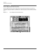
Cabling and Power Up MP Core I/O Connections The MP Main Menu appears: Figure 4-42 MP Main Menu Configuring LAN Information for the MP To set the server MP LAN IP address: 1. At the server MP Main Menu prompt (MP>), enter cm. From the MP Command Menu prompt (MP:CM>), enter lc (for LAN configuration). The screen lists the default values and asks if you want to modify them. It is a good idea to write down the information, as it may be required for future troubleshooting.
Cabling and Power Up MP Core I/O Connections Enter lc and press the Return key. The following screen appears: Figure 4-43 NOTE The lc Command Screen The value in the “IP address” field was set at the factory. The customer must provide the actual LAN IP address. 2. At the prompt, Do you want to modify the configuration for the customer LAN?, enter y. The current IP address is shown; then the following prompt appears: Do you want to modify it? (Y/[N]) 3. Enter y. 4. Enter the new IP address.
Cabling and Power Up MP Core I/O Connections 8. When step 7 is complete, the system indicates the parameters have been updated and returns to the MP Command Menu prompt (MP:CM>). 9. To check the LAN parameters and status, enter the ls command at the server MP Command Menu prompt (MP:CM>). 10. A screen similar to the following appears allowing verification of the settings: Figure 4-44 The ls Command Screen To return to the server MP main menu, enter ma. To exit the server MP, enter x at the MP main menu.
Cabling and Power Up MP Core I/O Connections Examining the MP Bus Devices To determine what is seen by the MP in the system: 1. At the server MP prompt, enter cm. The Command Menu is displayed. With the Command Menu, you can view or modify the configuration and look at utilities controlled by the MP. To look at a list of the commands available, enter he. You may have to press Enter to see more than one screen of commands. Use the Page Up and Page Down keys to view the previous or next screen of commands.
Cabling and Power Up Configuring AC Line Status Configuring AC Line Status Utilities can detect if power is applied to each of the AC input cords for the Server Expansion Unit. This detection is achieved by sampling the status of the bulk power supplies. During installation, use the following procedure to check the configuration for the AC line status and configure it to match the customer’s environment. NOTE Connection to the MP is performed through the core I/O card installed in the server.
Cabling and Power Up Applying 48V Power to the Server Expansion Unit and to the HP 9000 rp8400 server Applying 48V Power to the Server Expansion Unit and to the HP 9000 rp8400 server 48V power will we suppplied to the HP 9000 rp8400 server and the Server Expansion Unit after pressing the power switch. Core I/O card FPGA and MP revisions will be verified in the following procedure. Step 1. Press the power switch on the front of the Server Expansion Unit. Step 2.
Cabling and Power Up Applying 48V Power to the Server Expansion Unit and to the HP 9000 rp8400 server Step 4. Verify the new core I/O card FPGAs (2.008) and MP (4.013) revisions using the sysrev command. MP:CM> sysrev Cabinet FPGA and Firmware revision report System Backplane : GPM PCI Backplane FM OSP --- --- --- 1.002 1.002 1.002 : LPM HS --- --- 1.002 1.000 LPM BOB Drain SINC PDC --- --- ----- ---- --- CELL 0 : 2.002 1.000 1.001 2.002 17.005 CELL 1 : 2.002 1.000 1.
Cabling and Power Up Applying 48V Power to the Server Expansion Unit and to the HP Integrity rx8620 server Applying 48V Power to the Server Expansion Unit and to the HP Integrity rx8620 server NOTE This procedure only applies to servers other than the HP 9000 rp8400 server. See “Applying 48V Power to the Server Expansion Unit and to the HP 9000 rp8400 server” on page 90 when connecting the Server Expansion Unit to the HP 9000 rp8400 server.
Index A ac power voltage check, 78 login name MP, 84 ls (LAN Status) command , 87 B backplane, 10 mass storage, 12 PCI-X, 4, 10 system, 4, 10, 11, 12, 14 BPS (Bulk Power Supply), 84 M MAC address, 86 Management Processor (MP) , 83 mass storage backplane, 12 MP login name, 84 password, 84 MP (Management Processor) logging in, 84 powering on, 84 MP core I/O, 9, 13, 14, 30, 82, 83 MP network name, 86 MP/SCSI, 82 C cable management arm, 26, 27 cell board, 10, 11, 14, 83, 92 cm (Command Menu) command, 88 co