
Installation Guide, Third Edition - Server Expansion Unit

Chapter 1
Introduction
Server Expansion Unit Overview
4
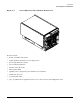
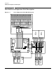
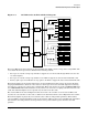
Server Expansion Unit System Backplane
The backplane board provides inter-connection between the PCI-X backplane and the core I/O backplane. The
backplane also provides a connection point for the system bus adapter (SBA) link cables and routes the SBA
link cable signals to and from the PCI-X backplane board. The backplane receives primary (48V) and standby
(12V) power from the bulk power supplies and distributes this power to loads on the backplane and to the
other boards connected to it. Besides providing interconnect, the backplane also contains clock generation
circuits, manageability circuits, DC-to-DC converters, power monitor logic, and fan control.
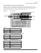
Core I/O Backplane Module
The core I/O backplane is housed in a separate sheet metal module holding the backplane and the core I/O
boards. This module can be removed from the rear of the chassis for easy access to the core I/O backplane.
This module adapts the core I/O sockets in a horizontal mounting position to the system backplane, which is
mounted vertically. It contains the lower bus adapter (LBA) PCI bridges that convert the ropes links from the
PCI backplane to the PCI bus interface where the core I/O card is inserted.
It also drives the PCI clocks and voltage regulators that provide domain power to the core I/O cards.
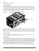
Core I/O PCA
There are two core I/O boards plugged into the Server Expansion Unit system when shipped. The core I/O
boards are oriented horizontally and are accessed from the back of the Server Expansion Unit. They are not a
standard PCI form factor. Each core I/O contains the required core functions to support a partition in a
server. Each also contains a manageability processor (MP).
Neither of the MPs on the core I/O cards installed in the Server Expansion Unit can become the master MP
for the server and Server Expansion Unit combination. The master MP for the server and Server Expansion
Unit will always be one of the core I/O cards installed in the server.
When a server with a Server Expansion Unit is attached and configured for four partitions, there must be
four core I/O boards, one for each partition. For this configuration, one core I/O card in the server is the
master MP and will provide all of the server management functions. The second core I/O in the server is the
slave MP. The third and fourth core I/O cards located in the Server Expansion Unit have similar master and
slave characteristics but only within the Server Expansion Unit itself. Overall system management for the
combination of the server and the Server Expansion Unit is managed by the master core I/O in the server.
Console data from the Server Expansion Unit is directed to the server.
The core I/O cards in the Server Expansion Unit support the mass storage and removable media devices and
make them available to the server in the same manner as the servers internal devices. The core I/O card in
the upper slot is the slave core I/O card in the Server Expansion Unit and is associated with cell 3 in the main
server cabinet. The core I/O card in the lower slot is the master core I/O card in the Server Expansion Unit
and is associated with cell 2 in the main server cabinet.