
Installation Guide, Third Edition - Server Expansion Unit

Chapter 1
Introduction
Server Expansion Unit Overview
6
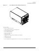
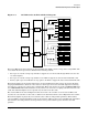
keyed for 3.3V connectors (accepting both Universal and 3.3V cards). One rope from each of the two SBA
ASICs connects to an LBA ASIC on the Core I/O Backplane board. Each of these two LBAs provides a PCI bus
that connects to an associated core I/O board.
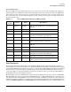
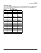
NOTE There is one single rope PCI slot for each cell. Slot 8 has a single rope associated with it so the
bandwidth is one-half the bandwidth for PCI cards installed in slots 1–7. Priority in installing
PCI cards should be given to slots with double ropes since they have double the bandwidth of a
single rope slot. See Table on page 7 for details.
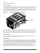
The PCI-X backplane contains an altimeter circuit. This circuit is used to adjust the chassis fan speeds for the
operating altitude at power on and during MP initialization. The chassis fans consist of the two front fans, the
two rear fans, and the six PCI-X I/O assembly fans. If an altimeter failure is detected, the information is
logged as an Event ID then propagated to the OS level to be picked up by monitoring diagnostics.
The altimeter circuit is checked at power on by the MP. If an expected value is returned from the altimeter
circuit, the altimeter is determined good. The altimeter reading is then set in non-volatile random access
memory (NVRAM) on board the core I/O card. If the value is ever lost like for a core I/O replacement, the
NVRAM will be updated at next boot provided the altimeter is functioning normally. If the altimeter has
failed, and the stable storage value has been lost because of a core I/O failure or replacement, the MP will
adjust the fan speeds for sea level operation.
NOTE Fans driven to a high RPM in dense air cannot maintain expected RPM and will be considered
bad by the MP leading to a “False Fan Failure” condition.
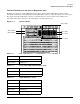
Voltage Regulator Modules on PCI-X Backplane
There are four voltage regulator modules (VRM) located on the PCI-X backplane. All four VRMs are
low-voltage modules. VRM 1 and VRM 3 provide power to cell 2 PCI-X slots. VRM 2 and VRM 4 provide power
to cell 3 PCI-X slots. The status for the PCI-X VRMs can be viewed by issuing the “ps”command from the MP
command prompt.