
Installation Guide, Third Edition - Server Expansion Unit

Chapter 1
Introduction
Detailed Server Expansion Unit Description
15
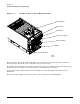
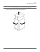
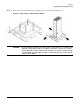
Figure 1-8 Right-Rear View of the Server Expansion Unit
The PCI-X I/O card section, located toward the rear, is accessed by removing the top cover.
The core I/O cards are positioned horizontally at the rear of the chassis. One core I/O card is positioned
directly above or below the other core I/O card. The Server Expansion Unit ships with both core I/O cards
installed in the chassis.
The PCI card bulkhead connectors are located in the top rear portion of the chassis.
Access to the system backplane is accomplished by removing the left side cover. The system backplane inserts
by a guide or insertion mechanism using a single large jack screw assembly.
Redundant line cords attach to the AC connector module at the bottom rear. One 20-amp cord is required to
supply power to the Server Expansion Unit. One additional line cord provides power source redundancy.
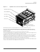
Four OLR system fan modules, externally attached to the chassis, are 120-mm (4.7-inch) fans. Two fans are
mounted on the front surface of the chassis and two are mounted on the rear surface.
There is an I/O manageability link connector to the right of the upper core I/O card. An external RS-485 cable
is used to connect between the Server Expansion Unit and the server.
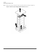
PCI-X I/O Card Section
PCI Card Bulkhead
Core I/O Card
Rear OLR Fan
AC Connector
System Backplane
I/O Manageability Link