
Installation Guide, Third Edition - Server Expansion Unit


Chapter 2
Installation
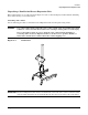
Unpacking the Server Expansion Unit
27
Installing Server Expansion Unit without a Mechanical Lift
Use this procedure only if an HP approved lift is not available.
This procedure should only be performed by two qualified HP Service technicians utilizing proper lifting
techniques and procedures.
System damage can occur through improper removal and re-installation of devices. This task must be
performed by trained personnel only. Instructions for removing and re-installing these components can be
found in the Removal & Replacement chapter of the Service Guide.
CAUTION Observe all ESD safety precautions before attempting this procedure. Failure to follow ESD
safety precautions could result in damage to the server.
Any hp Server Expansion Unit installed into a rack is shipped with equipment slides. With every set of slides
comes an installation guide: installation guide, hp J1530B, rack integration kit (lower case intended). Follow
the steps in this installation guide to determine where and how to place the Server Expansion Unit into the
rack before proceeding with Step 1. on page 27. The installation guide may also be found on the Web at
http://www.hp.com/racksolutions
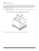
Step 1. Reduce the weight by removing both bulk power supplies.
Step 2. Locate the four positioning handles on the sides of the system. They are color coded blue and are
located close to each base corner of the unit.
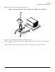
Step 3. Unfold the handles so they extend out from the unit. The unit is now ready for manual lifting by
two qualified HP Service technicians.
Step 4. After the Server Expansion Unit is secured in the rack cabinet, re-install the previously removed
bulk power supplies.
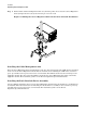
Installing the Cable Management Arm
After the Server Expansion Unit is installed in the rack, the CMA must be installed on the rear of the Server
Expansion Unit. Follow the instructions for installing the CMA in the installation guide, hp J1530B, rack
integration kit (lower case intended). The CMA is attached to the rack using screws supplied in the kit. The
other end of the CMA is attached to the Server Expansion Unit using custom nuts supplied in the kit. The
installation guide is on the Web at http://www.hp.com/racksolutions
Installing the Rack Interlock Device Assembly
After the cable management arm (CMA) is installed on the rear of the Server Expansion Unit then the
interlock device assembly must be installed. Follow the instructions for installing the interlock device
assembly in the installation guide, hp J1530B, rack integration kit (lower case intended). The installation
guide is on the Web at http://www.hp.com/racksolutions