
Installation Guide, Third Edition - Server Expansion Unit


Chapter 4
Cabling and Power Up
HP 9000 rp8400 server Upgrade and SBA Cable Installation
41
Shroud Verification
If the Server Expansion Unit comes factory-integrated in a cabinet with the server, then the shrouds are
already installed on the server backplane at the factory. There is no need to upgrade the shrouds on the
server backplane, in this case.
The shroud assembly kit ships with every Server Expansion Unit that will be racked in the field (rather than
already racked at the factory) and connected to a HP 9000 rp8400 server. Not every HP 9000 rp8400 server
requires the installation of the shroud assembly kit. There are two methods to determine if the shroud kit
needs to be installed.
Method 1
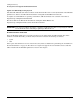
Remove the left side cover of the HP 9000 rp8400 server. Visually compare the shrouds attached to the
system backplane on the HP 9000 rp8400 server to the shrouds in the shroud assembly kit. The shrouds in
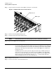
the assembly kit are made from brass and include a finger electromagnetic interference (EMI) gasket along
the top edge. The old style shrouds on the system backplane are black. Black shrouds need to be replaced with
the new style shrouds.
Figure 4-1 New Backplane Shroud with EMI Gasket
Method 2
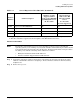
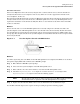
Check the engineering date code (EDC) for the HP 9000 rp8400 server backplane. The EDC can be checked
through the display FRU (DF) command at the MP:CM> prompt.
Step 1. Enter df at the MP:CM> system prompt.
Step 2. Select s for the system backplane in the HP 9000 rp8400 server.
Step 3. When asked to enter the cabinet number, enter 0 for the HP 9000 rp8400 server.
Step 4. Check the Engineering Date Code output for a revision level of A6-4320 or higher. The
Engineering Date Code output is circled in the following graphic.
NOTE The following graphic shows an older revision level for the EDC. It indicates that the
shrouds will need to be updated on the HP 9000 rp8400 server backplane.
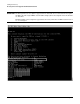
Step 5. Replace the shrouds if the EDC code is not at the minimum level established in step 4.
See the MP command output screen capture for the proceeding steps in the following graphic.
EMI gasket