
Installation Guide, Third Edition - Server Expansion Unit

Chapter 4
Cabling and Power Up
HP 9000 rp8400 server Upgrade and SBA Cable Installation
49
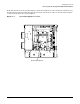
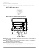
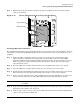
b. Continue pressing the shroud on the corners onto the board so that the short pins protruding
from the backplane are allowed to fit into the mating holes in the shroud. Refer to Figure 4-9.
Figure 4-9 Shroud Mating Holes
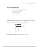
c. Tighten the previously removed T-15 TORX screw to secure the shroud to the board.
d. Press the shroud on the corners again to seat the pins in the shroud.
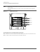
e. The shroud should lie flush or almost flush (within 0.5mm) to the system backplane.
Additionally, when the shroud is properly seated on the backplane, it will lock over the short
backplane grounding pins and remain seated while the screw is attached.
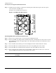
Figure 4-10 Shroud Position When Seated on the Backplane
The shroud should remain in place on the board once the pins are seated.
Holes in the Bottom
of the Shroud
Shroud Gap
Grounding Pins