
Installation Guide, Third Edition - Server Expansion Unit

Chapter 4
Cabling and Power Up
HP 9000 rp8400 server Upgrade and SBA Cable Installation
52
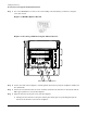
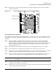
Step 8. Complete the procedure by securing the remaining three SBA cables in place with the captive
screw located on each SBA cable.
See Figure 4-13 for SBA cable orientation.
Figure 4-13 SBA Cable Orientation
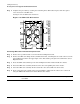
Connecting SBA Cables to the Server Expansion Unit
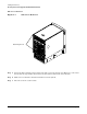
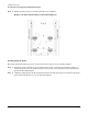
Step 1. Remove the top and left side covers from the Server Expansion Unit.
Step 2. Remove the SBA cable bridge bracket, hold-down bracket, and filler plates located at the rear of the
Server Expansion Unit in the upper right corner. Discard the parts just removed from the Server
Expansion Unit.
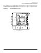
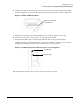
Step 3. Route the SBA cable bundle up to the Server Expansion Unit and then inside the chassis.
Step 4. Insert the SBA cable assembly bracket tab into the corresponding slot in the chassis.
Step 5. Screw the SBA cable assembly bracket attached to the cable bundle into the chassis.
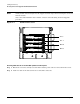
Step 6. Route cables along the outside of the system backplane and match the cables to the connectors
using the REO Cable Instructions label affixed to the chassis.
NOTE The term REO on the REO Cable Instructions label has the same meaning as the
term SBA.