
Installation Guide, Third Edition - Server Expansion Unit

Chapter 4
Cabling and Power Up
HP Integrity rx8620 server and HP 9000 rp8420 server SBA Cable Installation
67
Connecting SBA Cables to the Server
The cables will be routed inside the server chassis and connected to the shrouds on the server backplane.
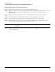
Step 1. Remove the SBA cable bridge bracket, located at the rear of the server chassis in the upper right
side, by turning the two thumbscrews counterclockwise. Lift the U-shaped SBA hold-down bracket
positioned behind the SBA cable bridge bracket up and away from the chassis. With a screwdriver,
gently pop the filler plates away from the chassis. Discard the parts just removed from the server.
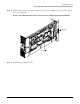
Step 2. Insert the SBA cable assembly bracket tab into the corresponding slot in the server chassis.
Step 3. Screw the SBA cable assembly bracket attached to the cables into the server chassis.
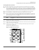
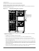
Step 4. Route each cable along the outside of the backplane down to the shrouds. Match each cable to the
shroud connector using the key on the REO Cable Instructions label affixed to the chassis on the
upper left-hand side as you face the backplane.
NOTE The term REO on the REO Cable Instructions label has the same meaning as the
term SBA.
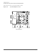
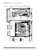
Step 5. Snap each cable under the cable clamps provided on the chassis frame. For cable to cable clamp
positioning, refer to Figure 4-29 on page 70.
Step 6. Push the cable on the connector and secure the SBA cable attached to the shroud by tightening the
captive screw attached to the SBA cable.
Step 7. Complete the procedure by securing the remaining three SBA cables in place with the captive
screw located on each SBA cable.
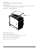
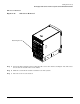
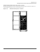
See Figure 4-27 for SBA cable orientation.
Figure 4-27 SBA Cable Orientation