
User Service Guide, Fourth Edition - Server Expansion Unit


Chapter 2
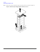
Site Preparation
Environmental Specifications
6
Environmental Specifications
This section provides the environmental, power dissipation, noise emission, and air flow specifications for the
Server Expansion Unit.
Temperature and Humidity
The cabinet is actively cooled using forced convection in a Class C1-modified environment. The recommended
humidity level for Class C1 is 40 to 55% relative humidity (RH).
Operating Environment
The system is designed to run continuously and meet reliability goals in an ambient temperature of 5°C–35°C
at sea level. The maximum allowable temperature is derated 1° C per 1000 feet of elevation above 5000 feet
above sea level up to 30° C at 10,000 feet. For optimum reliability and performance, the recommended
operating range is from 20° C to 25° C. This meets or exceeds the requirements for Class 2 in the corporate
and ASHRAE standard.
Environmental Temperature Sensor
To ensure that the system is operating within the published limits, the ambient operating temperature is
measured using a sensor placed near the chassis inlet, between the cell boards. Data from the sensor is used
to control the fan speed and also to initiate system overtemp shutdown.
Non-Operating Environment
The system is designed to withstand ambient temperatures between -40° C and 70° C under non-operating
conditions.
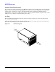
Cooling
Internal Chassis Cooling
The cabinet incorporates front-to-back airflow across the system backplane. Two 120-mm fans, mounted
externally on the front chassis wall behind the cosmetic front bezel, push air into the unit; and two 120-mm
fans housed in cosmetic plastic fan carriers and mounted externally to the rear chassis wall, pull air through
the unit.
Each fan is controlled by a smart fan control board, embedded in the fan module plastic housing. The smart
fan control board receives fan control input from the system fan controller on the system backplane and
returns fan status information to the system fan controller. The smart fan control board also controls the
power and the pulse width modulated control signal to the fan and monitors the speed indicator back from the
fan. The fan status LED is driven by the smart fan control board.
Bulk Power Supply Cooling
Cooling for the bulk power supplies is provided by two 60-mm fans contained within each BPS. Air flows into
the front of the BPS and is exhausted out of the top of the power supply though upward facing vents near the
rear of the supply. The air is then ducted out of the rear of the chassis.