
User Service Guide, Fourth Edition - Server Expansion Unit


Chapter 4
Troubleshooting
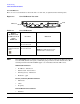
Common Installation Problems
31
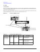
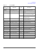
Table 4-7 Core I/O LEDs
LED (as
silk-screened on
the bulkhead)
Driven by State Description
MP PWR 3.3V standby power rail On Green Indicates standby power is on
ACTIVE Management processor On Green This core I/O is managing the
system
MP SEL On Green Both switches are in position F1
(silk-screened on the core I/O board)
for systems other than the rp8400.
Off Both switches are in position F0
(silk-screened on the core I/O board)
for rp8400 systems.
MP FAULT On Yellow Core I/O not fully seated or the MP
processor is being reset
MP LAN ACT MP LAN controller On Green Indicates MP LAN activity
MP LAN 10 BT MP firmware controlled On Green MP LAN in 10 BT mode
MP LAN 100 BT MP firmware controlled On Green MP LAN in 100 BT mode
MP LAN LINK MP LAN controller On Green MP LAN link is ok
SYS LAN ACT System LAN controller On Green Indicates SYS LAN activity
SYS LAN 10 BT System LAN controller On Green SYS LAN in 10 BT mode
SYS LAN 100 BT System LAN controller On Green SYS LAN in 100 BT mode
SYS LAN 1Gb System LAN controller On Green SYS LAN in 1Gb mode
SYS LAN FDUP System LAN controller On Green SYS LAN full duplex activity
SYS LAN LINK System LAN controller On Green SYS LAN link is ok
SCSI LVD System SCSI controller On Green SCSI LVD mode (on = LVD, off = SE)
SCSI TRM System SCSI controller On Green SCSI termpower is on
PWR LBA on system backplane On Green I/O power on
ATTN LBA on system backplane On Yellow PCI attention