
User Service Guide, Fourth Edition - Server Expansion Unit


Chapter 5
Removal and Replacement
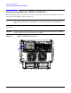
Removing and Replacing a DDS-4 or DVD Drive
52
Replacing a DDS-4 or DVD drive
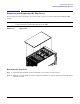
NOTE If you are replacing a DDS-4 or DVD drive component in the lower tray, the upper DDS-4 or
DVD drive component must be removed to have access to the lower DDS-4 or DVD drive cables.
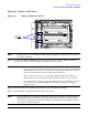
Step 1. Visually inspect the replacement part for proper number and revision.
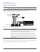
Step 2. Verify that the jumpers are set correctly.
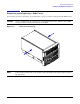
Step 3. Connect the cables to the rear of the DDS-4 or DVD drive.
NOTE DDS-4 or DVD drive components include removable rails attached to both sides. If
the component is to be replaced, ensure that the replacement component includes the
plastic rails. If the rails are not included, extract the pin that holds each rail, remove
the rail, and install both rails on the replacement component.
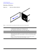
There are two sets of holes on each side of the DDS-4 or DVD drive component.
Ensure that the rails are mounted so that the pins fit into the bottom set of holes.
One of the rails has a locking tab attached. Ensure that the rail with the locking tab
is mounted on the left side of the DDS-4 or DVD drive component, as shown in
Figure 4-9, above.
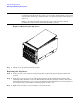
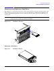
Step 4. Slide the drive in the chassis. Fold the cables out of the way.
Step 5. The drive easily slides into the chassis; however, a slow firm pressure is needed for proper seating.
Step 6. The front locking tab will latch to secure the disk drive in the chassis.
Factory Default =
N/A
Eject Enable -
Eject Disable -
7
6543218
2048 / 512
Termination ON OFF
N/A
01234567
SCSI ID