
BladeSystem p-Class Power Extension Kit Installation Instructions

Warnings and cautions
WARNING: This equipmen
t must be installed
by a licensed electrician or
trained service personnel
familiar with high-power circuitry.
These symbols, on power supplies or
systems, indicate that the
equipment is
supplied by
multiple sources of power.
WARNING: To reduce the risk
of injury from electric
shock, remove all power cords to completely
disconnect power from the system.
• Each power enclosure has two or more power
supply cords. A single rack
or cabinet may contain
more than one power en
closure. Power may be
supplied in a redundant fashion. Removing any
single source of power does not necessarily
remove power from any portion of the system.
When performing any servi
ce other than hot-plug
module replacement, you must completely
disconnect all power to that
portion of the system.
• When performing service procedures on server
blade enclosures,
ensure that both A and B DC
power feeds are disconnect
ed from the enclosure
before servicing.
• When performing service procedures on power
enclosures, shut off the circuit breakers to both A
and B AC power feeds and then disconnect both
power cords from the wall ou
tlet before servicing.
CAUTION: Electrostatic discharge (ESD) can
damage electronic components. Be sure that you are
properly grounded (eart
hed) before beginning any
installation procedure.
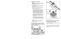
Connecting the DC power cables
from the upper 3U power enclosure
to the junction box
Repeat the steps for side B.
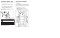
Mounting the junction boxes and
routing the power cables
Secure the upper junction boxes into the rack so that they do
not interfere with existing cables or the mini bus bars when the
bus bars are closed and secured.
Route the free end of the power
cables inside the rack between
the rack and the rails. Be sure that the cables will not become
trapped or damaged when the bus bars are opened or closed.
Secure the cables to the rack with the cable ties supplied in the
hardware kit.