HP BladeSystem p-Class System Overview and Planning Introduction......................................................................................................................................... 3 Executive summary............................................................................................................................... 3 HP BladeSystem modular architecture key benefits ...............................................................................
ProLiant BL20p, BL25p, BL30p, BL35p, and BL45p series server blades............................................ 38 Integrity BL60p Server Blades ...................................................................................................... 38 Operating system support ............................................................................................................... 38 HP ProLiant Essentials Rapid Deployment Pack.............................................................................
Introduction This white paper provides an overview of the HP BladeSystem p-Class solution. This solution includes: • Server blades • Server blade enclosures • Network interconnect options • Power subsystem components • Management tools Executive summary The HP BladeSystem p-Class solution consists of server blades, server blade enclosures, network interconnect options, a power subsystem, and management tools that enable adaptive computing and is optimized for rapid deployment.
HP BladeSystem modular architecture key benefits • Rapid deployment/redeployment saves valuable time – Server blades and interconnect switches can be installed and ready for immediate automated provisioning – Easy access to most pluggable components from the front of the rack, including server blades, hot-plug hard drives, and interconnect options – Easily add server blade capacity as needed without disrupting the system • Innovative design dramatically cuts network and power cables compared to traditional
HP BladeSystem manageability key benefits • Quickly configure both server blades and interconnect switches from a centralized deployment console using HP ProLiant Essentials Rapid Deployment Pack (RDP).
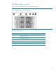
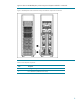
HP BladeSystem overview Figure 1 shows an HP BladeSystem p-Class Server Blade Enclosure. Figure 1. HP BladeSystem standard server blade enclosure Table 1.
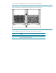
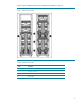
Figure 2 shows an HP BladeSystem p-Class 1U Power Enclosure installation. Figure 2. HP BladeSystem p-Class Enhanced Server Blade Enclosure and 1U Power Enclosure Table 2.
Figure 3 shows an HP BladeSystem p-Class 3U power subsystem installed in a 42U rack. Figure 3. HP BladeSystem 3U Power Enclosures and power distribution components in a 42U rack Table 3.
Figure 4 shows scalable and mini bus bar configurations installed in a 42U rack. Figure 4. Scalable and mini bus bars Table 4.
Hardware components The HP BladeSystem p-Class solution consists of the following: • Server blades • Server blade enclosures • Network interconnects • Power subsystem Table 5. HP BladeSystem Required Components Required Components Function Server blade Server blades contain one or more processors, memory, internal and external storage options, and integrated management. For FC connectivity, server blades must also be configured with FC card or FC HBA options.
ProLiant BL20p and BL25p series server blades The ProLiant BL20p and BL25p series Server Blades are ideal for infrastructure and enterprise applications, including: • Web • E-commerce • Server-based computing • AV and streaming media • Messaging front-end and mobility • Small database Figure 5. ProLiant BL20p G3 Server Blade Figure 6.
Table 6.
Figure 7. ProLiant BL25p Server Blade Table 7. Features of the ProLiant BL25p Server Blades ProLiant BL25p Server Blade Processor Up to two AMD Opteron™ 200 Series processors Internal storage Up to two universal hot-plug SCSI hard drives connected to the server through a SCSI Smart Array 6i Controller provide up to 600 GB capacity Memory Eight DIMM slots enable installation of up to 16 GB of PC3200 DDR, ECC, Registered SDRAM. The memory is 2x1 interleaved for added performance.
Figure 8. ProLiant BL30p Server Blade Table 8. Features of the ProLiant BL30p and ProLiant BL35p Server Blades ProLiant BL30p Server Blade ProLiant BL35p Server Blade Processor Up to two Intel Xeon processors Up to two AMD Opteron™ 200 Series processors per server blade. Lower power consumption per server enables use of more server blades for a given power consumption Internal storage Up to two small form factor (SFF) ATA hard drives provide up to 120 GB capacity.
ProLiant BL40p and BL45p Server Blades The ProLiant BL40p Server Blade is ideal for the following applications: • Medium to large enterprise databases • Messaging and collaboration • IPC Clustering/Failover Clustering • E-commerce • Server consolidation • Enterprise Resource Planning (ERP) • Customer Relationship Management (CRM) • Data Warehousing • Large file/print or domain controllers Figure 9.
Figure 10. ProLiant BL45p Server Blade Table 9.
Integrity BL60p Server Blade The Integrity BL60p Server Blade is ideal for the following applications: • HP-UX v11 applications • HP-UX legacy application consolidation • HP-UX test and development, particularly PA-RISC to Itanium migration • Database tier in applications requiring enterprise class HP-UX Unix Figure 11. Integrity BL60p Server Blade Table 10. Features of the Integrity BL60p Server Blade ProLiant BL60p Server Blade Processor Up to two Intel® Itanium2 1.
ProLiant and Integrity BL p-Class server blade SAN connectivity The ProLiant and Integrity BL p-Class server blades are optimized for HP StorageWorks arrays, and can attach to select third-party SAN solutions. In addition, the server blades can integrate with "fused" NAS and SAN configurations, providing the ability to work in file and block environments seamlessly.
Figure 12. BL20p G3 Dual Port FC Mezzanine Card (installed) Figure 13. BL25p/BL45p Dual Port FC Adapter Figure 14.
FC connectivity with ProLiant BL40p Server Blades ProLiant BL40p Server Blades have two external PCI-X slots for use with standard FC HBAs. When configuring ProLiant BL40p Server Blades with FC HBAs, the FC signals are not routed through the signal backplane. Refer to the documentation included with the ProLiant BL40p Server Blade for details. Figure 15. RJ-45 Patch Panel 2 installed in a server blade enclosure with ProLiant BL40p Server Blades and FC option Table 11.
FC port aggregation is required to accommodate the increased number of server FC HBA ports and to maintain compatibility with the available enclosure backplane signals and interconnect ports. The p-Class sleeve aggregates the four paths from two ProLiant BL30p or ProLiant BL35p Server Blades into two physical paths.
Figure 16 is a front view of the HP BladeSystem p-Class Blade Enclosure. Figure 16. Server blade enclosure front view Features of the server blade enclosure include: • Management communication—The server blade management module reports thermal, power, and protection fuse events to all server blades in the blade enclosure. The management module also facilitates power sharing across enclosures and provides asset and inventory information.
Figure 17 is a rear view of the HP BladeSystem p-Class Enhanced Server Blade Enclosure. Figure 17. Enhanced server blade enclosure rear view HP BladeSystem p-Class Blade Sleeve The HP BladeSystem p-Class Sleeve is required to support ProLiant BL30p and ProLiant BL35p Server Blades in the enhanced server blade enclosure. The sleeve is for use with these server blades only. Figure 18.
HP BladeSystem p-Class network interconnect options Each server blade enclosure must be configured with a pair of network interconnects. These interconnects slide into the front of the blade enclosure and collect Ethernet and FC (except ProLiant BL40p Server Blades) signals from all the installed server blades. Figure 19.
Table 12.
Each CGESM reduces up to 16 internal server blade network NIC ports to six external Ethernet ports. Because each external Ethernet port can communicate to all the server blades, as few as one external port per enclosure may be used to connect to your network. In addition to providing up to 32-to-1 network cable reduction per server blade enclosure, the CGESM kit offers the following features: • Cisco IOS based on Catalyst 2970 Enhanced Image. • Gigabit Ethernet performance on all switch ports.
The GbE2 Interconnect Kit contains two hot-plug, fully managed, layer 2 GbE2 Interconnect Switches and two LAN interconnect modules. The GbE2 Interconnect Kit is available with either copper-based (CgbE) or fiber-based (FgbE) uplinks. Each GbE2 Interconnect Switch reduces up to 16 internal server blade network NICs ports to six external Ethernet ports.
Figure 22. GbE Interconnect Switch components Table 15. GbE Interconnect Switch Components Item Description 1 GbE Interconnect Switch 2 GbE LAN Interconnect Module In addition to providing up to 32 FC to 1GB network cable reduction per server blade enclosure, the GbE Interconnect kit offers the following features: • DLink Switch OS. • Gigabit Ehternet performance on two uplink switch ports. • Advanced network feature support and system availability, including QoS, IGMP, and MAC-based priority.
ProLiant BL p-Class RJ-45 Patch Panel The RJ-45 Patch Panel brings all server blade NIC signals out as individual RJ-45 connectors. Figure 23. RJ-45 Patch Panel components Table 16.
ProLiant BL p-Class RJ-45 Patch Panel 2 The RJ-45 Patch Panel 2 functions as an Ethernet pass-through and enables pass-through functionality for FC signals from all server blades configured with internal FC adapter options. Figure 24. RJ-45 Patch Panel 2 components Table 17.
HP BladeSystem p-Class power subsystem HP provides two power subsystem alternatives to accommodate various environments and customer needs. These two options are enclosure-based power and rack-centralized power. All server blades, interconnect options, and management tools are fully compatible with either power subsystem.
HP offers two models of 3U power enclosure that are designed to meet installation power demand and redundancy requirements, depending on the number and type of server blades you plan to deploy: • Single-phase HP BladeSystem 3U p-Class Power Enclosure (holds up to four power supplies) • Three-phase HP BladeSystem 3U p-Class Power Enclosure (holds up to six power supplies) Because the three-phase power enclosure holds up to six power supplies, it supports more server blades and interconnect switches than the
Table 18. HP BladeSystem p-Class Power Distribution Options Solution Power Enclosures Supported Server Blade Enclosures Supported Maximum Rack Space Occupied Scalable bus bar 2 5 36U Mini bus bar 2 3 24U Power bus box 1 1 9U 1 2 1. To attach two power enclosures to a mini bus bar, the Dual Power Input Kit for Mini Bus Bar option is required. 2. To deploy a full 42U rack of HP BladeSystem p-Class server blades requires stacking two pairs of mini bus bars.
Table 19.
HP BladeSystem p-Class Diagnostic Station The HP BladeSystem p-Class Diagnostic Station enables a server blade or interconnect switch to be powered up outside of a server blade enclosure for testing or diagnostic purposes. The diagnostic station contains a power supply and connectors for data transfer between the server blade or interconnect switch and a client device (such as a PC, notebook, or workstation).
HP BladeSystem p-Class diagnostic and local I/O cables HP BladeSystem p-Class systems are optimized for use with HP ProLiant Essentials Rapid Deployment pack (RDP) for software installation and deployment from a centralized deployment console. Local console and I/O connections are available through diagnostic and local I/O cables. • Diagnostic cable—A diagnostic connector is on the front of the some server blade models.
HP BladeSystem Management Software overview HP highly recommends that you become familiar with the tools shown in Table 20, which are used to set up, configure, and manage the HP BladeSystem solution. This table serves as a getting started checklist and as a pointer to more information about these tools. The Integrity BL60 server blade supports only the HP-UX 11i operating system. There are management differences for this server. Please see http://www.hp.com/products1/servers/integrity/index.
Table 20: Key Management Components (continued) Tool Function Where to Find HP BladeSystem Interconnect Switch configuration and management software ProLiant BL Interconnect Switches provide both command line and Web-based interfaces for configuration and management of interconnect switches within server blade enclosures. For more information, refer to: Ships with HP BladeSystem p-Class Interconnect Switch Kits. HP BladeSystem p-Class GbE and GbE2 Interconnect Switches at http://h18004.www1.hp.
HP ProLiant Essentials Rapid Deployment Pack RDP provides a remote console-based method for scalable, automated server deployment without network degradation. RDP can be used to deploy from up to 100 server blades in 30 minutes. In addition, RDP for Windows (version 1.40 or later) includes the added ability to identify and deploy interconnect switches.
HP SIM also helps keep blade BIOS, drivers, and agents up to date through system software version control. HP SIM will automatically download the latest firmware components from the HP website and identify systems that require updates, either by comparing target servers to a customer-defined system software baseline or to the latest software published by HP. Users can then deploy single components or collections of components to groups of systems using the "Install Software and Firmware" task.
For more information on the Smart Array 6i Controller, refer to http://h18006.www1.hp.
HP BladeSystem p-Class Interconnect Switch Management The HP BladeSystem p-Class GbE and GbE2 Interconnect Switches are industry-standard managed Ethernet switches that customers configure and manage in the same manner as other industry-standard Ethernet switches. To aid users during initial deployment, the interconnect switch includes a default configuration that is fully operational at initial boot.
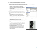
Planning for a HP BladeSystem p-Class installation The HP BladeSystem p-Class Sizing Utility is a free, flexible, graphical tool that provides valuable information necessary to help plan and prepare a site for delivery and installation of HP BladeSystem p-Class solutions and order the necessary components for the installation. Site planning information, such as power requirements and environmental specifications, is generated based on user-defined system configuration criteria.
Figure 31. HP BladeSystem Equipment List Output Example Equipment List This Equipment List can be copied to an excel worksheet or word document. To copy this table, select the table using the mouse. Copy the selected table using Copy command from the Edit menu. Go to the destination document and paste it. Part Description Qty Part Number ProLiant BL20p server blace with ONE Pentium lll P1400-512K, 512MB RAM, no drives 4 230040-B21 ProLiant BL40p server blade with ONE Xeon MP1.
Figure 32: Maximum output power capacity For more information about the HP BladeSystem p-Class Sizing Utility, refer to http://www.hp.com/go/bladesystem/sizingutility Facility DC power connection Facility DC power requires a Facility DC Power Connection Option Kit to distribute the current through the mini or scalable bus bars to the server blade enclosures. The HP BladeSystem p-Class system requires –48 VDC with no more than ±10% voltage variance.
Figure 33. 3U power enclosure connectors AC connectors for the 3U power enclosure Table 21 shows the four models of power enclosure connectors that are available. Table 21. Power Enclosure Connectors and Compatibility Item Two Circuits/ Connectors Model Typical Electrical Service 1 L6-30 NA 1-phase (239162-001) Single-phase 208 VAC 2 L15-30 NA 3-phase (230769-001) Three-phase delta 208 VAC 3 3-pin (2-pole + ground) Intl.
Deployment considerations: HP BladeSystem p-Class network interconnects The RJ-45 Patch Panel, RJ-45 Patch Panel 2, GbE Interconnect Switches, and GbE2 Interconnect Switches may be mixed within the rack, but not within the same server blade enclosure. The corresponding interconnect modules may also be mixed within the rack, but not within the same server blade enclosure.
The optional GbE2 Storage connectivity kit provides pass-through of ProLiant BL20p, ProLiant BL25p, ProLiant BL30p, BL35p, and ProLiant BL45p FC signals. This kit includes two OctalFC interconnect module connect modules, each with eight SFF slots. The SFF transceivers with LC connectors shipped with each BL20p G3, BL25p, or BL45p Dual Port FC Mezzanine Card are installed in the OctalFC SFF slots.
Table 23: Ethernet and FC Cable Requirements (continued) Interconnect Ethernet FC F-GbE2 Interconnect Kit 1 to 8 optical cables with LC connectors per server blade enclosure Requires Storage Connectivity Kit 1 to 4 cables per server blade enclosure 1 cable for the centralized server blade management module on enclosures with enhanced backplane components Storage Connectivity Kit N/A Same as RJ-45 Patch Panel 2 Deployment considerations: ProLiant BL p-Class GbE Interconnect Switches The C-GbE Interc
Server Blade Quantity For site planning, the assumed quantity of server blades should be the total number of server blades that will be deployed over the life of the installation. Planning for growth is necessary to ensure that you purchase the appropriate power subsystem components (power enclosures and bus bars) and quantities of server blade enclosures. Additionally, growth sizing enables the pre-configuration of ample power to ensure that the HP BladeSystem can be expanded as your business grows.
Site recommendations The HP BladeSystem p-Class Sizing Utility provides environmental load estimates (total DC and AC power consumption, generated heat in BTU, weight and floor space requirements) based on the configuration. This information can be useful when planning and managing the data center environment. For more information about the HP BladeSystem p-Class Sizing Utility, refer to http://www.hp.
Total floor space To enable servicing and adequate airflow, observe the following spatial requirements when deciding where to install an HP, Compaq, telco, or third-party rack: • Leave a minimum clearance of 63.5 cm (25 in) in front of the rack. • Leave a minimum clearance of 76.2 cm (30 in) in the back of the rack. • Leave a minimum clearance of 121.9 cm (48 in) from the back of the rack to the rear of another rack or row of racks.
© 2005-2006 Hewlett-Packard Development Company, L.P. The information contained herein is subject to change without notice. The only warranties for HP products and services are set forth in the express warranty statements accompanying such products and services. Nothing herein should be construed as constituting an additional warranty. HP shall not be liable for technical or editorial errors or omissions contained herein. Microsoft and Windows are U.S. registered trademarks of Microsoft Corporation.