
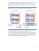
HP BladeSystem p-Class rack-centralized (3U) power solutions

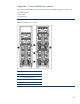

Maximum AC-redundant configurations for HP BladeSystem
server blades
Tables 3, 4, and 5 in this section provide general guidelines for maximum 42U rack configurations
with AC redundancy. The maximum configurations are based on either physical constraints or
maximum power loads and are the same for 208V or 220V inputs. The guidelines were calculated
using these assumptions:
• All server blades in a rack are the same model
• All models are configured with the maximum number of processors, memory, and two disk drives
• All configurations use the GbE2 interconnect switches
• All server blades are running at or near 100 percent average utilization rates using three-phase
power
Therefore, actual server blade requirements may be significantly less than the maximum if server
blades are configured with less hardware or are used at lower average workloads. It follows that
these maximum rack configurations can be exceeded if the blade servers are configured with fewer
processors, less memory, and so on.
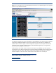
The tables below are only examples of possible configurations. Refer to the
HP BL p-Class Sizing
Utility to determine specific requirements.
6
NOTE: Customers can build larger rack configurations if they do
not require AC redundancy. It is also possible to build a six-
enclosure rack using the 1U power enclosure.
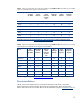
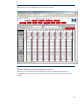
Table 3. Maximum configurations for ProLiant server blades using mini-bus bars, three-phase power of 208V
input or higher, N+N redundant power supplies, and redundant AC.
Server Max
processors
per blade
Max blades
per 6U
enclosure
Max 6U
blade
enclosures
per 42U
rack
Max
blades per
42U rack
Power
supplies
required
3U power
enclosures
required
BL20p G3 2 8 5 40 24 4
BL25p 2 8 5 40 24 4
BL30p 2 16 5 80 24 4
BL35p 2 16 5 80 24 4
BL40p 4 2 5 10 24 4
BL45p 4 4 5 20 24 4
BL60p 2 8 5 40 24 4
6
The HP BladeSystem Sizing Utility is available at http://h30099.www3.hp.com/configurator/calc/BL p-
Class.xls
12