
HP BladeSystem p-Class rack-centralized (3U) power solutions

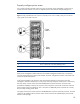

Properly configure power zones
For a system to function properly when using two mini bus bar power subsystems or when using a
mixed 1U and 3U solution in a rack, two separate power zones must be configured (Figure 6).
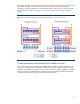
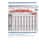
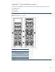
Figure 6. A fully populated 42U rack requires two separate power zones to identify which power enclosures
supply specific server blade enclosures.
Item Description
1 Zone 1 switches set in the down (default) position
2 Zone 2 switches set in the up (secondary) position
Each power management module and each server blade management module has a two-position
switch for setting the power zone for that module. All power configuration switches in the same zone
must be set to the same position.
As of firmware release 2.20, however, there are important changes in how power zones are
managed. In firmware releases prior to 2.20, there were only two power zones (zone 1 and zone 2)
that were set by a switch on the rear of HP BladeSystem 3U power enclosures. Firmware 2.20
provides the capability to have up to six power zones. The power zone switch on the rear of the 3U
power enclosure only has settings for zone 1 and zone 2; additional power zones start at 3 so they
do not overlap existing power zones.
For legacy firmware, the switch remains on HP BladeSystem 3U power enclosures; however, firmware
versions 2.20 and above do not use the switch. Power zones are set automatically by the firmware,
based on rack topology.
18