
HP BladeSystem c-Class architecture Technology brief, 4th edition

13
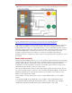
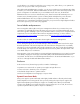
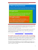
Figure 10: Separation of the transmit and receive signal pins in the interconnect bay connector
For more information about what we did to ensure signal integrity, see “Electrical signal integrity
considerations for HP BladeSystem” available at
http://h20000.www2.hp.com/bc/docs/support/SupportManual/c01712559/c01712559.pdf.
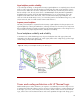
Channel topology and equalization settings
Even when using best practices, insertion and reflection losses can degrade high-speed signals
transmitted across multiple connectors and long PCB traces. Insertion losses, such as conductor and
dielectric material losses, increase at higher frequencies. Impedance discontinuities, primarily at
connectors cause reflection losses. To compensate for these losses, shape the transmitter’s signal
waveform by selecting signal equalization settings. But a transmitter’s equalization settings depend on
the end-to-end channel topology and the type of component sending the signal. Both topology and the
transmitting component can vary in the BladeSystem c-Class because of the flexible architecture and
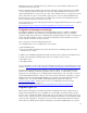
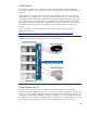
the use of mezzanine cards and NICs or other embedded I/O devices. As shown in Figure 11, the
topology for device 1 on server blade 1 (a b c) is different from the topology for device 1 on server
blade 4 (a-d-e). So, a link configuration mechanism in the Onboard Administrator (assisted by iLO on
each server blade) identifies the channel topology for each device and configures the proper
equalization settings for that device.
Figure 11: Different instances require different equalization settings
Interconnect Bay Connector
Receive Signal Pins
Transmit Signal Pins
Ground plane
Switch-1 PCB
Midplane
PCB
Switch
Device
Onboard
Administrator
c
d
e
Server blade-1
a
DEV-1
Server blade-4
a
DEV-1
b