HP Integrity BL860c Server Blade Installation Guide HP Part Number: AD217-9014C Published: November 2011 Edition: 5
© Copyright 2007, 2011 Hewlett-Packard Development Company, L.P Legal Notices The information contained herein is subject to change without notice. The only warranties for HP products and services are set forth in the express warranty statements accompanying such products and services. Nothing herein should be construed as constituting an additional warranty. HP shall not be liable for technical or editorial errors or omissions contained herein. Printed in U.S.A.
Contents About This Document.....................................................................................5 Intended Audience....................................................................................................................5 New and Changed Information in This Edition..............................................................................5 Publishing History.....................................................................................................................
Accessing EFI or the OS from iLO 2 MP.....................................................................................31 EFI Boot Manager..............................................................................................................32 Saving EFI Configuration Settings....................................................................................32 Booting and Installing the Operating System..........................................................................
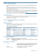
About This Document This document provides information and instructions on servicing the HP Integrity BL860c server blade. The document publishing date and part number indicate the document’s current edition. The publishing date changes when a new edition is updated. The document part number changes when extensive changes are made. Document updates may be issued between editions to correct errors or document product changes.
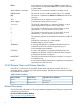
Ctrl+x A key sequence. A sequence such as Ctrl+x indicates that you must hold down the key labeled Ctrl while you press another key or mouse button. ENVIRONMENT VARIABLE The name of an environment variable, for example, PATH. ERROR NAME The name of an error, usually returned in the errno variable. Key The name of a keyboard key. Return and Enter both refer to the same key. Term The defined use of an important word or phrase. User input Commands and other text that you type.
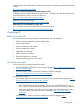
Find information about administration of the Microsoft Windows operating system at the following website: http://www.microsoft.com/technet/ Diagnostics and Event Monitoring: Hardware Support Tools Complete information about HP hardware support tools, including online and offline diagnostics and event monitoring tools, is on the HP website at: http://www.hp.com/go/hpux-diagnostics-docs Website for HP Technical Support http://welcome.hp.com/country/us/en/contact_us.
Subscription Service HP recommends that you register your product at the Subscriber's Choice for Business website: http://www.hp.com/country/us/en/contact_us.html. Documentation Feedback HP welcomes your feedback. To make comments and suggestions about product documentation, send a message to docsfeedback@hp.com. Include the document title and manufacturing part number. All submissions become the property of HP.
1 Installing the Server Blade Into the Enclosure This chapter covers the procedures for installing the server blade into a c-Class enclosure. Safety Information When removing and replacing server components, use care to prevent injury and equipment damage . Many assemblies are sensitive to damage by electrostatic discharge.
Verify Site Preparation Verifying site preparation is an essential factor of a successful server installation, and includes the following tasks: • Gather LAN information. Determine the two IP addresses for the Integrated Lights Out 2 Management Processor (iLO 2 MP) LAN and the server blade LAN. • Establish a method to connect to the server console. For more information on console connection methods, see Section : “Accessing the Integrated Lights Out 2 Management Processor” (page 23).
Service Tools Required Service of this product can require the following tools: • An IPF Processor Install Tool Kit, consisting of: • Disposable ESD Kit • Processor installation tool (2.5 mm hex and Torx 15 screwdriver) NOTE: If you purchased an additional processor, the IPF Processor Install Toolkit is included with the processor. The server blade has a Torx T–15 screwdriver mounted on the inside of the access panel.
2. Close the lever to lock the drive into place (2). Figure 2 Installing a Hot-Plug SAS Disk Drive Installing Internal Components Use these procedures to install internal components that were not installed into your server blade. Before you can install the internal components, you must remove the access panel. Removing the Access Panel To remove the access panel: 1.
Figure 3 Removing the Server Blade Access Panel After the access panel is off, you can do the following: • Add an additional processor. See “Installing a Processor” (page 13). • Add additional memory DIMMs. See “Installing DIMMs” (page 15). • Add additional mezzanine cards. See “Installing Mezzanine Cards” (page 16) Installing a Processor Use this procedure to install an additional processor into the server blade. To install a processor: 1.
Figure 4 Unlocked ZIF Socket CAUTION: Do not tighten the ZIF socket lock more than 180 degrees in either direction. This severely damages the socket and processor, and renders the processor slot unusable. 3. Install the processor into processor slot 1 on the system board by lining up the alignment pins on the processor with the holes in the processor slot. NOTE: Processor 0 is already installed in the server blade. See Figure 5 for slot locations on the server blade system board.
7. Tighten the captive screws (5 – 6) on the processor with the Torx T-15 screwdriver until snug Figure 6 Installing a Processor on the Server Blade System Board 8. Connect the power cable to the processor power connector using the clips shown circled in Figure 6 (page 15). If you are only adding a processor to your server blade, and not adding memory DIMMs or mezzanine cards, go to “Replacing the Access Panel” (page 20). If you are adding DIMMs, go to “Installing DIMMs” (page 15).
1. Locate the DIMM slots on the server blade system board. See Figure 7. NOTE: The server blade ships with at least two DIMMs installed in slots 0A and 0B. Figure 7 DIMM Slot Locations 2. Ensure the DIMM slot latches are open. CAUTION: Use only HP low profile (1.2 in.) DIMMs. DIMMs from other sources might adversely affect data integrity. DIMMs do not seat fully if turned the wrong way. DIMMs in a pair must be identical. 3. Insert a DIMM in a slot and push down firmly until the latches click shut.
Figure 8 Mezzanine Port Locations on the System Board 1 2 3 The 1. 2. 3. Mezzanine port 1: PCIe x4 port Mezzanine port 2: PCIe x8 port Mezzanine port 3: PCIe x8 port install order for the mezzanine cards is: PCIe x4 card – Install into mezzanine port 1 PCIe x8 card – Install into mezzanine port 2 PCIe x8 card – Install into mezzanine port 3 If you are only loading PCIe x8 cards, install them into port 2, then port 3.
Figure 9 Mezzanine Port Heights Installing a Mezzanine Card in Port 1 To insert a mezzanine card into the PCIe x4 port 1 on the system board: 1. Line up the plastic pins on the mezzanine card connector with the PCIe x4 port on the system board. 2. Push down on the card directly above the port to seat the card into the port (1).
3. Tighten the thumbscrews on the mezzanine card until snug to secure the card to the system board (2). See Figure 10. Figure 10 Mezzanine Card 1 Installed on the Server Blade System Board Installing a Mezzanine Card to Ports 2 and 3 To insert a mezzanine card into the PCIe x8 ports 2 and 3 on the system board: 1. Line up the plastic pins on the mezzanine card connector on the PCIe x8 port 2 on the system board. 2. Push down on the card directly above the port to seat the card into port 2 3.
6. Tighten the thumbscrews on the mezzanine card until snug to secure it to the system board. Figure 11 shows all three mezzanine cards installed on the server blade system board. Figure 11 Mezzanine Cards 2 and 3 Installed on the Server Blade System Board 1 2 3 Mezzanine card 1 (PCI–e x4) Mezzanine card 2 (PCI–e x8) Mezzanine card 3 (PCI–e x8) Replacing the Access Panel To replace the access panel: 1. Make sure the access panel latch is in the open position (pointing up). See Figure 12 (page 21). 2. 3.
Figure 12 Replacing the Access Panel 4. Lock the access panel cam (if necessary) by turning the cam clockwise with the Torx T–15 or flathead screwdriver. Installing and Powering On the Server Blade This section describes how to install the server blade into a standard c-Class enclosure and power it on. When you install the server blade into the enclosure, the server blade powers up to standby mode.
5. Close the extraction lever (2). The server blade should come up to standby power. The server blade is at standby power if the server health LED is amber. IMPORTANT: If the server health LED turns green, and the fan noise gets louder, then the server blade has powered on. Skip the rest of this procedure, and proceed to “Accessing the Integrated Lights Out 2 Management Processor” (page 23).
power on to standby power when installed in a server blade enclosure. Verify the power state by looking at the LEDs on the front panel, and using Table 4. For more front panel LED information, see the HP Integrity BL860c Server Blade User Service Guide.
2. Use the down arrow on the front display panel to highlight Blade or Port Info. Figure 14 shows the Blade or Port Info selection highlighted on Main Menu of the front display panel. Figure 14 Main Menu of the Front Display Panel 3. Press OK. The View Blade and Port Info screen displays on the front display panel. See Figure 15. Figure 15 The View Blade and Port Info Screen 4. 5. 24 Using the left/right arrows, highlight Blade Info on the bottom of the front display panel.
Figure 16 The View Blade Info Screen 6. 7. 8. 9. Write down the iLO 2 MP IP address that displays on the View Blade Info screen. Access the iLO 2 MP through telnet, SSH, or through the web using the assigned DHCP IP address. This ends the “Accessing the iLO 2 MP with DHCP Enabled” procedure. Continue to “Configuring the iLO 2 MP” (page 27). Accessing the iLO 2 MP with No Network Connection You need to have a terminal emulator (for example, a laptop using hyperterm) to connect to the server blade.
Figure 17 Connecting the SUV Cable to the Server Blade Connecting a Terminal to the Server Blade To establish a connection from your server to your terminal (or emulator device): CAUTION: Disconnect the SUV cable from the port when not in use. The port and connector are not intended to provide a permanent connection. 1. Connect the standard DB9f to DB9f modem eliminator cable to the RS-232 port on the SUV cable. See Figure 18. Figure 18 Serial Connector on the SUV Cable 2.
4. 5. 6. 7. To set the parameters, click OK. If running an emulator, launch it now. This ends the “Accessing the iLO 2 MP with No Network Connection” procedure. Continue with “Configuring the iLO 2 MP” (page 27). Configuring the iLO 2 MP Use this procedure to configure iLO 2 MP settings after establishing a connection to iLO 2 MP using one of the two methods discussed in Section : “Accessing the Integrated Lights Out 2 Management Processor”.
iLO 2 MP Security Requirements Depending on how you set up your server blade, there are security concerns regarding whether you allow remote access to the server blade. It is highly recommended that you allow remote access to the server blade. Remote access allows for remote system event log analysis, troubleshooting, and general system administration. During the login process, a warning message displays. If you log in through a terminal (serial or telnet) an ASCII message scrolls by.
2. Enter on to set the power restore configuration to power on to full power as shown below: 3. 4. Enter y to confirm changing the power restore configuration setting. Power on the server through the iLO 2 MP by accessing the Power Control menu. Access the Power Control menu by entering pc from the MP Main Menu. 5. Enter on to power on the server blade as shown below: 6. Enter y to confirm changing the power control setting.
Remote Access Allowed NOTE: If your server blade has a DHCP server connected to the OA/iLO port on the rear of the enclosure, this procedure is not required. Proceed to “Accessing EFI or the OS from iLO 2 MP” (page 31). To allow remote access, you should have changed your iLO 2 MP password to secure your server blade. If you have a DHCP server connected to the OA/iLO port on the rear of the enclosure, your access is set.
Remote Access Not Allowed If you do not want to allow remote access to the server blade, use the following steps to disable DHCP and other remote connections on your server blade. CAUTION: Only use this procedure if you are disabling remote access to the server blade. Do not disable remote access if you have a DHCP server connected to the OA/iLO port on the rear of the enclosure. This procedure disables all remote access to the server blade and you lose your remote access the server blade. 1. 2.
• From the MP Main Menu, enter co to access the Console Menu. Depending on how the server blade was configured from the factory, and if the OS is installed at the time of purchase, you should be in one of two places: • EFI Boot Manager menu • OS login prompt If the server blade has a factory-installed OS, you can interrupt the boot process to configure your specific EFI parameters. If you are at the EFI Shell prompt, go to “EFI Boot Manager” (page 32).
Server Blade to Enclosure Interface This section describes the interface between the server blade and the server blade enclosure. This sections also shows the RJ-45 LAN interconnect ports on the rear of the server blade enclosure, and how they correspond with the Network Interface Controller (NIC) LEDs on the front of the server blade. Port Locations on the Rear of the Server Blade Enclosure LAN port mapping depends on the type of I/O card that is installed into the server blade.
Table 5 Server Blade to Enclosure Interconnect Mapping (continued) Server Blade to c-Class Enclosure Mapping Mezzanine Slot 2 Slots 5 and 6 Mezzanine Slot 3 Slots 7 and 8 NOTE: Dual-width interconnect modules cannot be used in slots 1 or 2. Only single- or dual-port mezzanine cards are supported. LAN / NIC Configuration Table 6 shows how the EFI and HP-UX LAN ports and front panel NIC numbers match up on the server blade enclosure.
3. To determine the current version of the firmware: a. At the EFI Shell, enter mptutil from the directory that contains mptutil.efi. The following example indicates that the EFI Serial Attached SCSI card utility version is 1.01.12.00: fs0:EFI\HP\TOOLS\NETWORK> mptutil MPTUTIL-1.01.12.00 Vendor Device Choice ID ID Bus Device ------ ------ ------ --- -----0 1000h 0054h 14h 01h LSI Logic SAS1068 Host Adapter 1 - Refresh b. 4. 5. Press Enter. To update the firmware, use the mptutil command.
Common Questions About Flashing Firmware Question After I update firmware on my SAS HBA, why doesn't the version string change in the menu? Answer The firmware you flashed on the HBA does not run until a diagnostic reset occurs. If you exit the utility and reenter it, the version string is updated. Question This image does not contain a valid nvdata image when I try to flash the firmware. Why? Answer You are expected to concatenate a proper nvdata image to the firmware.
There are general key inputs throughout the configuration utility that apply on all screens: F1 Help Context sensitive help for the cursor-resident field. Arrow Keys Select up, down, left, or right to position the cursor. Home/End Select up, down, left, or right to position the cursor. +/- Use to change items with values in [ ] brackets. Numeric keypad + and numeric keypad - (minus) update a modifiable field to its next relative value.
You can view and modify the SAS controller whether it is enabled or disabled. You can use the Boot Support setting in the Adapter Properties menu to change the status of this setting. You must reconnect the EFI Driver for a new Boot Support setting to take effect. The following are descriptions for the Adapter List screen.
PCI Address FW Revision Displays the PCI Address assigned by the system BIOS to the adapter. • Bus value range 0x00 - 0xFF, 0 - 255 decimal • Device value range 0x00 - 0x1F, 0 - 31 decimal • Function range 0x00 - 0x7, 0 - 7 decimal Displays the MPT firmware version and type. The format is x.xx.xx.xx-yy where: x.xx.xx.xx refers to the FW version yy refers to the type. The currently supported type is IR.l). SAS Address Displays the SAS Address assigned to this adapter.
Figure 22 Select New Array Type Screen Select New Array Type Screen The Select New Array Type screen enables you to view an existing array or create an Integrated Mirror array of two disks, plus an optional hot spare. • To go to the Create New Array screen, select Create IM Volume. • To go to the View Array screen, select View an Existing Array. Create New Array Screen The Create New Array screen enables you to create an array.
in an IM. You can specify a hot spare at array creation, or after creation, if the array uses five disks or fewer. This field is grayed out under the following conditions: Drive Status • The device does not meet the minimum requirements for use in an IM array. • The array has a hot spare. • The array is made up of the maximum number of devices (six). • The device isn't large enough to mirror existing data on the primary.
View Array Screen The View Array screen enables you to view the current array configuration. To access the View Array screen, press Enter on the View Existing Array field from the Select New Array Type screen. You can perform the following actions on the View Array screen: • To view the next array, press N. • To create a new array, press C. The following are descriptions for the View Array screen: Array Displays the number of this array. Identifier Displays the array identifier.
Offline Disk is offline for some other reason. Inactive Disk has been set inactive. Not Syncd Data on disk is not synchronized with the rest of the array. Primary Disk is the primary disk for a two disk mirror and is OK. Secondary Disk is the secondary disk for a two disk mirror and is OK. Wrg Type Device is not compatible for use as part of an IM array. Too Small Disk is too small to mirror data.
Synchronize Array To synchronize the IM array, press Enter on Synchronize Array. The screen prompts you to perform this action. Press Y for yes or N for no. This field is grayed out under the following conditions: • The array is inactive. • The array does not need to be resynchronized. • The adapter's MPT firmware does not support the feature • Non-IR firmware is used. • IR is disabled. The array is inactive. Activate Array To activate an IM array, press Enter for Activate Array.
Starting CFGGEN The 1. 2. 3. cfggen utility is located on the HP IPF Offline Diagnostic and Utilities CD. To use cfggen: Insert the CD into the drive. Boot the server to the EFI Shell prompt. From the EFI Shell prompt, change to the CD drive: shell> fs0: Enter fs0:> 4. Change to the directory that contains cfggen.efi. fs0:> cd EFI\HP\TOOLS\NETWORK Enter fs0: EFI\HP\TOOLS\NETWORK> 5. From this directory, use cfggen. CFGGEN Operation The cfggen command is not case sensitive.
CREATE Command The CREATE command creates IM volumes on the SAS controller. Firmware and hardware limitations for this family of cards limit the number of configurations that are possible. Syntax cfggen create [qsync] [noprompt] Parameters Volume type for the volume to be created. Valid value is IM. Size of the IM volume in megabytes, or “MAX” for the maximum size available. [qsync] Quick synchronization of the volume created.
Parameters A SAS controller number between 0 and 255. [DELETE] Specifies that the hot spare is to be deleted (omit the DELETE keyword to specify hot-spare creation). : Enclosure number and Bay number that identify the disk drive that becomes the hot spare. Operation The number of disks in an IM array plus the hot spare cannot exceed three. You can create only one hot spare disk.
5. 6. 7. Choose the OS. Choose the firmware category you want to download. Download the firmware to a CD. Install the Latest Version of Firmware on the Server To install the firmware on the server: 1. Connect to the server console. See “Accessing the Integrated Lights Out 2 Management Processor” (page 23). 2. Make sure the external USB DVD drive is connected and turned on. See the HP Integrity BL860c Server Blade User Service Guide. 3.
Index A F access panel removing, 12 replacing, 20 accessing iLO 2 MP, 23 allowing remote access, 30 antistatic wrist strap, 9 firmware downloading latest version, 47 installing latest version, 48 verifying latest version, 47 C c-Class enclosure see enclosure cfggen utility, 44 AUTO command, 46 CREATE command, 46 HOTSPARE command, 46 parameters, 45 starting, 45 checking the inventory, 10 chip sparing, 15 confirming the packing slip, 10 D damaged equipment, 10 DIMMs chip sparing, 15 installing, 15 load o
O U obtaining the enclosure name using the RB command, 29 unpacking the server blade, 10 P V PCI expansion blade, installing, 22 ports enclosure, 33 powering on default, automatically, 23 server blade, 23 setting auto power on, 28 processor installing, 13 slot locations, 14 VPD information for EFI driver and RISC firmware, 36 R RB command obtaining the enclosure name, 29 rear panel ports, 33 remote access allowing, 30 configuring, 29 disabling, 30, 31 securing, 28 removing access panel, 12 disk driv