HP ProLiant BL p-Class System Diagnostic Station User Guide Part Number 230859-003 September 2003 (Third Edition) HP CONFIDENTIAL Writer: Amy Clute File Name: 230859-3.
© 2003 Hewlett-Packard Development Company, L.P. Microsoft® and Windows® are U.S. registered trademarks of Microsoft Corporation. Intel® and Pentium® are U.S. registered trademarks of Intel Corporation. Java™ is a U.S. registered trademark of Sun Microsystems, Inc. Hewlett-Packard Company shall not be liable for technical or editorial errors or omissions contained herein. The information in this document is provided “as is” without warranty of any kind and is subject to change without notice.
Contents Abstract.......................................................................................................... 5 HP ProLiant BL p-Class System Diagnostic Station Kit Contents............ 6 Warnings and Cautions ................................................................................ 7 Using the Diagnostic Cable or the I/O Cable for Configuration or Diagnostic Procedures .................................................................................
Abstract This document explains the functions and uses of the diagnostic cable, the local I/O cable, and diagnostic station. This document also provides instructions for cabling the diagnostic station to an HP ProLiant BL p-Class server blade to enable out-of-rack communication with the server blade. HP ProLiant BL p-Class System Diagnostic Station User Guide HP CONFIDENTIAL Writer: Amy Clute File Name: 230859-3.
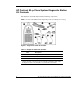
HP ProLiant BL p-Class System Diagnostic Station Kit Contents The diagnostic station kit ships with the following components. NOTE: You may need additional items, depending on the server blade you are using.
Table 1: Diagnostic Station Kit Contents continued Item Description 4 DC power cord (for server blade)2 5 DC power cord (for interconnect switch) 6 AC power cord3 7 Network cable with RJ-45 connectors 8 Data transfer cable Not shown Documentation CD-ROM Not shown This installation guide 2 For information about connecting the diagnostic station to an interconnect switch using this DC power cord, refer to the documentation that ships with the interconnect switch.
CAUTION: Properly ground yourself before beginning any installation procedure. Electrostatic discharge can damage electronic components. For more information about electrostatic discharge, refer to the setup and installation guide. CAUTION: Disconnect the I/O or diagnostic cable when not in use. The port and connector do not provide permanent connections.
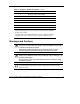
Identifying Diagnostic and I/O Cable Connectors Use Figure 3 and Table 2 to identify diagnostic cable and I/O cable connectors. Figure 3: Connectors Table 2: Diagnostic and I/O cable connectors Item Description Diagnostic cable (top) 1 Server blade connector 2 iLO 10/100 Ethernet RJ-45 connector 1 3 Kernel debug connector 2 1 A standard Ethernet cable can be used with the RJ-45 connector for a direct cable connection. 2 The kernel debug connector does not function as a serial port.
Table 2: Diagnostic and I/O cable connectors continued Item Description I/O cable (bottom) 3 4 Video connector 5 USB connector (2) 6 Kernel debug connector 2 7 iLO 10/100 Ethernet RJ-45 connector 1 8 Server blade connector 1 A standard Ethernet cable can be used with the RJ-45 connector for a direct cable connection. 2 The kernel debug connector does not function as a serial port. 3 The I/O cable is labeled with the I/O icon. The Diagnostic cable has no label.
Installing the Diagnostic Cable or the I/O Cable To install the diagnostic cable or the I/O cable with the diagnostic station, see the “Diagnostic Station” section. To install the diagnostic cable on a server blade in the rack, refer to the setup and installation guide included with the server blade. Diagnostic Station The diagnostic station enables you to power up and communicate with a server blade or an interconnect switch outside of the rack environment.
For more information about installing hardware options and performing troubleshooting procedures, refer to the p-Class server blade setup and installation guides on the Documentation CD and to the documentation that ships with the interconnect switch. Diagnostic Station Components Use Figure 4 and Table 3 to identify diagnostic station components.
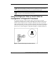
Table 3: Diagnostic Station Components continued Item Description 7 DC power output connectors 8 Data transfer port 9 NIC LEDs 10 Power On/Off button 11 Power and health LED Accessing the Cable Storage Area To access the cable storage area: 1. Turn the locking latch clockwise (1). 2. Pull down the cable storage area access door (2). Figure 5: Accessing the cable storage area HP ProLiant BL p-Class System Diagnostic Station User Guide HP CONFIDENTIAL Writer: Amy Clute File Name: 230859-3.
Client PC Requirements Observe the following minimum software and hardware requirements for a client PC: • Intel® Pentium® III or higher processor (700 MHz or greater recommended) • 128 MB of RAM • Microsoft® Windows® 2000 Professional or Microsoft Windows XP operating system • Microsoft Internet Explorer 5.
3. Place the server blade on a flat, level workspace. 4. Perform any upgrade or maintenance actions and replace the access panel. Cabling the Diagnostic Station to a Server Blade This document provides two methods for connecting the diagnostic station to a server blade: • Direct cabling methodUse either method to be sure an option is correctly installed in the server blade.
Using the Direct Cabling Method with a Client PC NOTE: Items in addition to those provided with the diagnostic station may be required. Additional items will be noted in the option kits they ship with. NOTE: The server blade in the illustrations may look different from the model you are using. WARNING: To avoid electric shock, be sure that the AC power is disconnected from the diagnostic station when connecting cables to the server blade.
3. Place the VHDM converter on the rear of the server blade by inserting the tab into the right side (1), making sure the pins on the left side are properly aligned. 4. Tighten the thumbscrew to secure the VHDM converter to the server blade (2). 5. Insert the DC power cord into one of the diagnostic station DC power connectors (3).
6. Connect the data transfer cable to the VHDM converter on the server blade (1). 7. Connect the other end of the data transfer cable to the diagnostic station (2). Figure 8: Connecting the data transfer cable 18 HP ProLiant BL p-Class System Diagnostic Station User Guide HP CONFIDENTIAL Writer: Amy Clute File Name: 230859-3.
8. Connect the server blade to the client PC using the diagnostic cable. If you are using the I/O cable to connect to the I/O port, go to step 9. IMPORTANT: Connecting the diagnostic cable to the diagnostic port automatically disables the iLO connection on the rear of the server blade. a. Connect the network cable with RJ-45 connectors to the client PC (1). b. Connect the other end of the RJ-45 network cable to the diagnostic cable (2). The kernel debug connector can remain unused. c.
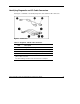
9. Connect the server blade to a client PC using the I/O cable. IMPORTANT: Connecting the I/O cable to the I/O port automatically disables the iLO connection on the rear of the server blade. a. Connect the network cable with RJ-45 connectors to the client PC (1). b. Connect the other end of the RJ-45 network cable to the I/O cable (2). The remaining connectors can remain unused. c. Connect the I/O cable to the I/O port on the front of the server blade (3).
IMPORTANT: The diagnostic station ships with several AC power cords of different outlet plug configurations. Be sure to select the proper AC power cord for the electrical service. 10. Connect the AC power cord to the diagnostic station (1). 11. Connect the other end of the AC power cord to an AC outlet (2). NOTE: Previously installed components have been removed for clarity.
Refer to Figure 12 for the completed direct cabling method using diagnostic cable (left) and the I/O cable (right). Figure 12: Completed direct cabling method (front and rear views) using the diagnostic cable (left) and the I/O cable (right) to connect to iLO After the direct cabling method is complete, the server blade and diagnostic station are ready for use. See the “Powering Up the Server Blade” section.
3. Connect the monitor to the video connector on the I/O cable. 4. Connect a USB hub to the USB connector on the I/O cable. NOTE: Use of the USB hub is optional as you may connect to the server using any combination of USB devices. For example, you may connect a monitor to the video connector and a USB mouse and USB keyboard to the USB connector. 5. Connect the following to the USB hub: a. USB CD-ROM and/or USB floppy b. USB keyboard c.
Using the Network Cabling Method In addition to the diagnostic station and contents, you need to supply the following items: • Client PC (See the “Client PC Requirements” section for minimum software and hardware requirements.
2. Connect the network cable with RJ-45 connectors to the diagnostic station NIC 4 connector (1), and to the hub (2). 3. Connect the AC power cord to the diagnostic station (3). NOTE: Previously installed components have been removed for clarity. Depending on which server blade you are using, you may need to install a second power supply in the diagnostic station. A second power cord would also be required.
4. Connect an additional network cable with RJ-45 connectors between the client PC (1) and the hub (2). Figure 15: Connecting a network cable to the client PC and the hub 5. Connect the following items to the hub: a. Network cable with RJ-45 connectors from the diagnostic station NIC 4 connector b. Network cable with RJ-45 connectors from the client PC c. DHCP server (optional), if not already connected d. Network cable with RJ-45 connectors from the diagnostic station NIC 1 connector (optional) e.
Figure 16 shows a completed network cabling method with the DHCP server (1) and the hub (2). IMPORTANT: For operating system deployment or file management, an optional server can be connected to the hub. NOTE: Connecting the diagnostic cable to the diagnostic port or connecting the I/O cable to the I/O port automatically disables the iLO connection on the rear of the diagnostic station.
NOTE: iLO may take up to 90 seconds to establish a secure network connection. iLO Guidelines for Accessing the Server Blade Use the following guidelines when you prepare to access the server blade with the iLO Remote Console for the first time. Two ways are available to make the wiring connections from the client PC to the iLO: the direct cabling method and the network cabling method.
• The TCP/IP address or DNS/WINS name of the iLO — When using the direct cabling method, use the 192.168.1.1 for the TCP/IP address and 255.255.255.0 for the subnet mask. — When using the network cabling method, look on the iLO Default Network Settings tag for first time access. • A valid user ID and password with appropriate iLO privileges for accessing Remote Console This information is also available on the iLO Default Network Settings tag for initial access information.
Regulatory Compliance Notices Regulatory Compliance Identification Numbers For the purpose of regulatory compliance certifications and identification, your product has been assigned a unique HP series number. The series number can be found on the product nameplate label, along with all required approval markings and information. When requesting compliance information for this product, always refer to this series number.
Canadian Notice This Class A digital apparatus meets all requirements of the Canadian InterferenceCausing Equipment Regulations. Avis Canadien Cet appareil numérique de la classe A respecte toutes les exigences du Règlement sur le matériel brouilleur du Canada.
Japanese Notice Korean Notice BSMI Notice 32 HP ProLiant BL p-Class System Diagnostic Station User Guide HP CONFIDENTIAL Writer: Amy Clute File Name: 230859-3.