
BladeSystem p-Class Power Extension Kit Installation Instructions
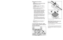

Connecting the DC power cables
from the lower 3U power enclosure
to the dual power box
IMPORTANT: HP recommends installing the mini bus bar
3U up from the bottom of the rack to provide adequate
space to mount the mini bus bar dual power boxes.
NOTE: Depending on the placement of the mini bus bar
kit on the rack, it may not be possible to mount the dual
power box as illustrated. Placement of the dual power box
on the mini bus bar is optional when installing the HP
BladeSystem p-Class Power Extension Kit.
Refer to the
HP BladeSystem p-Class Dual Power Input Kit
Installation Instructions
and to the following figure and table to
continue the installation.
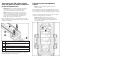
Item Description
1 DC power extension cables from upper 3U power
enclosure
2 DC power cables from lower 3U power enclosure
3 Power cables to bus bar
4 Mini bus bar dual power box
After completing the dual power kit installation, complete the
installation using the information below.
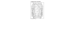
Connecting the management
cables
NOTE: Previously installed components have been
removed for clarity.
The load balancing cable enables load sharing between the two
power enclosures. Connect the load balancing cable (1) from
the lower 3U power enclosure to the upper 3U power enclosure.
Connect the management link cable (2) from the server blade
enclosure to the upper 3U power enclosure.
NOTE: Management modules are used only for
information management (asset tracking, for example).
Disconnecting the management module cabling does not
affect system operation.