HP BladeSystem Onboard Administrator User Guide Abstract This guide provides information on the initial setup and operation of the HP Blade System Onboard Administrator. It also covers use of the Onboard Administrator GUI and enclosure Insight Display. The information in this guide applies to Version 4.20 (or later) of the HP Blade System Onboard Administrator.
© Copyright 2006, 2014 Hewlett-Packard Development Company, L.P. The information contained herein is subject to change without notice. The only warranties for HP products and services are set forth in the express warranty statements accompanying such products and services. Nothing herein should be construed as constituting an additional warranty. HP shall not be liable for technical or editorial errors or omissions contained herein. Confidential computer software.
Contents Introduction .................................................................................................................................. 8 Overview ................................................................................................................................................. 8 Access requirements ................................................................................................................................ 10 Onboard Administrator overview .................
Features ................................................................................................................................................. 49 First Time Setup Wizard .............................................................................................................. 54 Before you begin..................................................................................................................................... 54 User Preferences .............................................
Active Onboard Administrator Module ..................................................................................................... 174 Active Onboard Administrator screen............................................................................................. 174 Active Onboard Administrator Virtual Buttons tab ............................................................................ 175 Active Onboard Administrator USB tab ......................................................................
Role-based user accounts .............................................................................................................. 267 Local Users ................................................................................................................................. 268 Directory Settings screen .............................................................................................................. 273 Uploading a certificate .............................................................
Oceanic time zone settings ..................................................................................................................... 334 Europe time zone settings ....................................................................................................................... 335 Polar time zone settings .......................................................................................................................... 335 Support and other resources ................................
Introduction Overview HP BladeSystem Onboard Administrator is the enclosure management processor, subsystem, and firmware base that supports the HP BladeSystem c-Class enclosure and all the managed devices contained within the enclosure. Onboard Administrator provides a single point from which to perform basic management tasks on server blades or switches within the enclosure.
server iLO, interconnect management processors such as Virtual Connect which use the Onboard Administrator/iLO management port such as Virtual Connect Administrator. Manager to other VC modules in the enclosure. Information and health status Yes. Complete control. reporting for all blades, interconnects, fans, power supplies, Onboard Administrators, and enclosure through Onboard Administrator's GUI or CLI, alert mail, or SNMP Yes. Complete control.
If redundant Onboard Administrator firmware versions do not match, the settings are not automatically synchronized. Synchronize the firmware by using the Insight Display, GUI, or CLI command, and then the settings are automatically synchronized to the replaced Onboard Administrator module. 2 Access requirements To access HP BladeSystem Onboard Administrator web interface, you must have the Onboard Administrator IP address and a compatible web browser.
NOTE: The Onboard Administrator supports multiple simultaneous login sessions, whether through the Onboard Administrator web interface or CLI, except for LDAP/Active Directory users where only one login session is allowed per user.
components in device bays in the front of each enclosure, Onboard Administrator communicates with iLO to control servers, and with a microcontroller to control options such as storage blades. A separate microcontroller controls power to the interconnect modules. After components are powered, the Onboard Administrator begins thermal management with Thermal Logic.
Onboard Administrator authentication Security is maintained for all Onboard Administrator user interfaces through user authentication. User accounts created in Onboard Administrator are assigned one of three privilege levels and granted access to component bays at the specified privilege level. Onboard Administrator stores the passwords for local user accounts and can be configured to use LDAP authentication for user group accounts.
When operating in FIPS Mode, configure FIPS Mode before performing any other enclosure or Onboard Administrator configuration, including configuration of the Virtual Connect or First Time Setup Wizard. Enabling FIPS Mode on an Onboard Administrator module or redundant pair of modules forces the Onboard Administrator modules to be reset to factory defaults. After configuring FIPS Mode, perform the configuration steps in this section. For more information on FIPS Mode, see "FIPS tab (on page 117).
each user account - or use the Administrator local account to individually update all user passwords after restoring a previously saved enclosure configuration file. If the enclosure contains redundant Onboard Administrator modules, the remaining Onboard Administrator updates the new Onboard Administrator with all the settings. Signing in to the Onboard Administrator GUI Enter the user name and initial administration password for your Onboard Administrator.
topmost enclosure to the "up-link" port of the following enclosure. Repeat until the bottom enclosure is reached. This GUI order is the same order that appears in the SHOW TOPOLOGY command. As shown in the preceding example, the enclosure table on the Sign-in page also provides information on the enclosure status, connection, firmware version, OA name, and rack position.
The following figure shows the extended data for the first enclosure listed in the table. Flash disaster recovery To successfully recover an Onboard Administrator from a failed flash, you must have the following: • Local access to the enclosure • A DHCP server accessible by the Onboard Administrator • A TFTP server accessible by the Onboard Administrator • Onboard Administrator firmware (.
a. With a null-modem cable (9600 N, 8, 1, VT100), locally connect to the Onboard Administrator. b. Press and hold the Reset button of the Onboard Administrator for 5 seconds. c. On the serial console, when you are prompted for Flash Recovery or Reset Password, do not type anything. Wait at least 2 minutes or more to let the Standby OA to become the Active OA before proceeding to the next step. d.
Using online help To access online help, click the blue box with the white question mark or Help located on the top right of the screen under the header bar. Online help displays information related to the section of Onboard Administrator in which you are navigating. Changing enclosure and device configurations After you have completed the First Time Setup Wizard, you can return to the Onboard Administrator GUI to make configuration changes at any time.
Alternatively, to reset a password on the Onboard Administrator, select the Insight Display (LCD panel) USB Menu option. This option restores a configuration script using command line interface commands stored on a USB key. NOTE: If the Insight Display USB menu buttons are locked, then the serial port method must be used. If the LCD panel is locked, then a large “lock” symbol appears on the screen. In this example, the OA Administrator password is set to Password123. 1.
BladeSystem network architecture overview All device bays, interconnect modules, and Onboard Administrator modules are connected to an internal enclosure network that is managed by the active Onboard Administrator. Network traffic from business applications running on server blades is routed through interconnect switch modules and onto the production network.
• Securing the Insight Display LCD panel The Insight Display LCD panel allows for configuration and monitoring of key Onboard Administrator settings: network address configuration and power up/down of server blade bays to name a few critical BladeSystem functions. HP recommends securing the Insight Display LCD panel with a PIN, particularly in a multi-tenant datacenter.
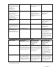
NOTE: When running a version of Onboard Administrator firmware earlier than version 3.70 with Strong Encryption mode enabled, if you update the firmware to version 3.70 or later, an entry might be logged to the Onboard Administrator syslog indicating that the Onboard Administrator is operating in FIPS Mode. This syslog entry ("FIPS: OA is operating in FIPS Mode On") is incorrect and can be ignored.
OA 3.70 OA 4.11 FIPS Mode OA 4.20 ON FIPS Mode ON OA 4.11 OA 4.20 OA 3.60 OA 3.60 OA 3.
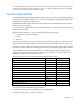
• aes128-cbc • 3des-cbc • aes192-cbc • aes256-cbc • rijndael-cbc@lysator.liu.se SSH key exchange algorithms • • • OA 4.11 and OA 4.20 diffie-hellman-group-exchange-sha1,diffie-hellman-group14-sha1,diffie-he llman-group1-sha1 OA 4.01 diffie-hellman-group-exchange-sha1,diffie-hellman-group14-sha1 OA 3.71 diffie-hellman-group-exchange-sha1,diffie-hellman-group14-sha1,diffie-he llman-group1-sha1 o OA 4.01 and later versions include an option to enable/disable diffie-hellman-group1-sha1. o OA 4.
HP BladeSystem c7000 Enclosure hardware installation Installing Onboard Administrator modules The HP BladeSystem c7000 Enclosure is shipped with one HP BladeSystem Onboard Administrator module installed and can support up to two Onboard Administrator modules. Install Onboard Administrator modules based on the total number ordered: • One Onboard Administrator module: Bay 1 • Two Onboard Administrator modules: Bays 1 and 2 Install an Onboard Administrator blank in an unused Onboard Administrator bay.
2. Slide the Onboard Administrator module into the Onboard Administrator tray, and close the handle. When the Onboard Administrator module is fully inserted, it locks into place. HP BladeSystem Onboard Administrator cabling Item Connector Description 1 Enclosure link-down port Connects to the enclosure link-up port on the enclosure beneath it using a CAT5 patch cable. 2 Enclosure link-up Connects to the enclosure link-down port on the enclosure above it using CAT5 patch port and service cable.
Item Connector Description 4 OA2/iLO Reserved for future Onboard Administrator connections. If the Onboard Administrator management Ethernet port is connected to a management LAN that also connects to server ports, be sure that the server applications do not overload the Onboard Administrator management port with broadcast packets.
HP BladeSystem Insight Display HP BladeSystem c7000 2-inch Insight Display components Item Description Function 1 Up arrow button Moves the menu selection up one position 2 Down arrow button Moves the menu selection down one position 3 OK button Accepts the highlighted selection and navigates to the selected menu 4 Left arrow button Moves the menu or navigation bar selection left one position 5 Right arrow button Moves the menu or navigation bar selection right one position 6 Insight Dis
HP BladeSystem c3000 and c7000 3-inch Insight Display components Item Description Function 1 Insight Display screen Displays Main Menu error messages and instructions 2 Left arrow button Moves the menu or navigation bar selection left one position 3 Right arrow button Moves the menu or navigation bar selection right one position 4 OK button Accepts the highlighted selection and navigates to the selected menu 5 Down arrow button Moves the menu selection down one position 6 Up arrow button
After two minutes of inactivity, the Insight Display flashes amber indicating an error or alert condition exists. If the enclosure UID is on and an error or alert condition exists, the Insight Display illuminates blue as the enclosure UID takes priority over the alert. Pressing any button on the Insight Display reactivates the screen. • Dark (no power)—The Insight Display has a two-minute inactivity period. If no action is taken and no alert condition exists, the screen light turns off after two minutes.
2. Pull the Insight Display out of the chassis to lock it into place, and then tilt it up. Running the Insight Display installation To identify the enclosure, the rear enclosure UID light and the background of the Insight Display are illuminated blue when the enclosure is powered on initially. When the enclosure is powered up for the first time, the Insight Display launches an installation wizard to guide you through the configuration process.
TIP: Select the ? icon to access detailed help information about each setting or topic. TIP: Within any menu option, navigate the cursor to What is This, and press the OK button to view additional information about each setting, option, or alert. 4. When all settings on the Enclosure Settings menu are accurate, move the cursor to Accept All, and press OK to accept the current settings. You can change the following options in the Enclosure Settings screen: Power Mode—The default setting is AC Redundant.
Enclosure Name—The default setting is a unique factory-assigned name. The accepted character values are 0–9, A–Z, a–z, -, _ and . The symbol is used to signal the end of the name. NOTE: Do not use the symbol in the middle of a text field. Entries in text fields will be truncated to the last character before the symbol. TIP: Select Clear from the navigation bar to quickly clear entries in text fields up to the symbol. Rack Name—The default setting is UnnamedRack.
The Blade DVD Connection menu indicates whether an Enclosure DVD or ISO file on a USB key is available to connect to the selected servers on the DVD Connect Status menu. If multiple ISO files are found on the USB key, you might see more than one page of options. To view the next page of connection options, select the Next Page button.
o Yes—Copy the configured power settings, rack name, and LCD Lockout PIN (if set) from the Enclosure Settings screen to the detected enclosures. o No—Continue configuring the current enclosure only. The Insight Display installation wizard must run on each detected enclosure. Select this option if each enclosure requires different power settings.
If no errors are detected, the rear enclosure UID powers off, and the Insight Display screen illuminates green. 10. To return to the Main Menu, press OK. Enclosure and blade hardware setup and configuration is complete. IMPORTANT: If errors are detected, the Insight Display screen illuminates amber, and the Health Summary screen displays. For more information on troubleshooting configuration errors, see "Insight Display errors (on page 46).
The Main Menu of the Insight Display has the following menu options: • Health Summary • Enclosure Settings • Enclosure Info • Blade or Port Info • Turn Enclosure UID on/off • View User Note • Chat Mode • USB Key Menu If the active Onboard Administrator detects KVM capability, a KVM menu button appears on the navigation bar on the Main Menu. Selecting KVM Menu causes the Insight Display to go blank and activate the VGA connection of Onboard Administrator.
Health Summary screen The Health Summary screen displays the current condition of the enclosure. The Health Summary screen can be accessed by: • Selecting Health Summary from the main menu • Selecting the Health Summary icon from any Insight Display screen When an error or alert condition is detected, the Health Summary screen displays the total number of error conditions and the error locations. Select Next Alert from the navigation bar, and press the OK button to view each individual error condition.
• Dynamic Power setting • Active and Standby OA IP addresses • Enclosure Name • Rack Name • DVD Drive • Insight Display PIN NOTE: The DVD Drive setting can attach or detach a CD or DVD loaded in the optional c3000 enclosure DVD drive to any or all server blades in the enclosure. This feature can be used to install an operating system or software on the server blade(s). If the optional DVD drive is not present, an external HP USB DVD drive can be used with this feature instead.
• Rack name Blade and Port Info screen The Blade or Port Info screen displays information about a specific server blade. On the first screen, select the server blade number, then press the OK button. Select Blade Info or Port Info, and press the OK button. If viewing a BL2x220c server, navigate right to the second selection box and use up or down to select server A or B. The right selection must be N/A to select all other server blade info screens.
To view information about the server blade, select Blade Info and press the OK button. To view the ports used by a specific server blade, select Port Info and press the OK button. On the full-height server blade shown below, there are four embedded NICs. The other interconnect bays are empty. The four embedded NICs are connected to particular port numbers on the interconnect modules.
Selecting Turn Enclosure UID On from the main menu turns on the rear enclosure UID LED and changes the color of the Insight Display screen to blue. Selecting Turn Enclosure UID Off from the main menu turns off the rear enclosure UID LED and changes the color of the Insight Display screen to the current condition.
View User Note screen The View User Note screen displays six lines of text, each containing a maximum of 25 characters. Use this screen to display helpful information such as contact phone numbers or other information. Change this screen using the remote Onboard Administrator user web interface. Both the background bitmap and the text can be changed. Chat Mode screen The Chat Mode screen is used by the remote administrator who uses the web interface to send a message to an enclosure Insight Display.
USB Menu screen Onboard Administrator firmware version 2.30 and later offers added support for the following USB key options: • Updating OA firmware • Restoring OA configuration • Saving OA Configuration Onboard Administrator supports USB keys formatted for FAT32 or EXT2 file systems. You can use either the port located on the active Onboard Administrator module on the front of the enclosure or a USB port on the optional KVM module. To access the USB Key Menu: 1.
• Restore Configuration—Select this option to upload an enclosure configuration file with .CFG extension. The Restore OA Configuration menu lists all the files on the attached USB key with .CFG file extensions. Select the desired configuration file and press OK to apply that configuration to the enclosure.
• Fix THIS—Suggests corrective action to clear the current error. • Next Alert—Displays the next alert, or if none exist, displays the Health Summary screen. • Previous Alert—Displays the previous alert. Power errors Power errors can occur because of insufficient power to bring up an enclosure. Power errors can occur on server blades, storage blades, or interconnect modules. To correct a power error: 1. Use the arrow buttons to navigate to Fix This, and press OK. 2.
o Remove the server blade to correct the mezzanine card installation (the Insight Display will indicate the correct bay). For information on installing the mezzanine card, see the server-specific user guide on the Documentation CD. Device failure errors Device failure errors occur when a component has failed.
Enclosure KVM Features The Enclosure KVM feature enables the Onboard Administrator to switch between server video consoles, using only an attached VGA monitor, USB keyboard, and USB mouse without requiring a PC. In addition to launching and running server video consoles, the Enclosure KVM Menu provides health status of each server and enables you to power servers on and off and attach an enclosure DVD to those servers. The Insight Display is deactivated (appears blank) while Enclosure KVM is active.
Returning to the KVM Menu from another interface To return to the KVM Menu from a server console, Insight Display, or the OA CLI display, press the Prt Scrn key on the USB keyboard. Returning to the Insight Display from the KVM Menu To restore the Insight Display and blank the KVM Menu (A slight delay may occur.), press any Insight Display button, or select Exit KVM on the KVM Menu. Navigating the KVM Menu The following figure shows the KVM Menu: To navigate the HP KVM Menu, use the keyboard arrow keys.
except PrtSc are sent to the server, along with the KVM mouse. To exit the server console and return to the KVM Menu, press Prt Scrn. NOTE: For resolutions 1024x768 through 1600x1200, the screen resolution matches the server console screen resolution. Server console resolutions below 1024x768 result with a display on a portion of the Onboard Administrator KVM screen in 1024x768 mode.
• OA CLI—Select OA CLI to launch the Onboard Administrator CLI. Log in to the Onboard Administrator using the KVM keyboard. This launches a full screen text console to the active Onboard Administrator CLI. To exit the Onboard Administrator CLI console and return to the KVM Menu, press Prt Scrn. • Help—Select Help to view the KVM help information. NOTE: When the Onboard Administrator is in FIPS mode, iLO security access setting, Enforce AES/3DES Encryption, must be enabled.
Enclosure KVM 53
First Time Setup Wizard Before you begin Before running the First Time Setup Wizard, complete the following tasks: 1. Install the Onboard Administrator modules. 2. Connect the Onboard Administrator modules to the network. 3. Complete the Insight Display installation wizard. At a minimum configure the active Onboard Administrator IP address. 4. Run the Insight Display installation. Signing in to Onboard Administrator 1.
You can return to previous wizard steps by selecting them in the left tree view. You can also run the wizard again at any time by selecting it from the Wizards menu. User Preferences To change the display language, select a display language from the list, and then click Apply. If you set a language preference in the Onboard Administrator GUI, the browser language setting will be overridden.
FIPS FIPS mode • FIPS mode OFF—Enables the use of non-FIPS-140-2-approved algorithms. • FIPS mode ON—Enforces the use of the Onboard Administrator in a FIPS 140-2-approved mode. This FIPS mode includes the use of approved algorithms such as AES, 3DES, SHA and other security restrictions. • FIPS mode DEBUG—Sets the Onboard Administrator to an environment similar to the FIPS mode ON, but with the option of debug support from HP.
The term FIPS mode used in this document and within the product is to describe the feature, and not its validation status. The FIPS validation process is lengthy, so not all versions are FIPS validated. For information about the current FIPS status of this or any other firmware version, see the following documents: • Cryptographic Module Validation Program FIPS 140-1 and FIPS 140-2 Modules In Process List (http://csrc.nist.gov/groups/STM/cmvp/documents/140-1/140InProcess.
• o If the configuration is not supported. The primary enclosure must be enabled for Two-Factor Authentication and both the primary and linked enclosures must have the same credentials for the linked enclosure to authenticate using Two-Factor Authentication. If the primary enclosure does not have Two-Factor Authentication enabled, then you cannot select the linked enclosure with Two-Factor Authentication enabled.
• USB file—You can select a configuration file on a USB key plugged into the enclosure. Select the appropriate configuration file from the dropdown list. After selecting the configuration file, click Apply. This option only appears if a USB key is plugged into the enclosure. After selecting the file location, a dialog box displays the results.
Field Possible value Description Time Zone Time zone settings The time zone assigned to the enclosure • • • • • • • Primary NTP Server • • • Secondary NTP Server • • • Africa time zone settings (on page 331) Americas time zone settings (on page 332) Asia time zone settings (on page 333) Universal time zone settings (on page 331) Oceanic time zone settings (on page 334) Europe time zone settings (on page 335) Polar time zone settings (on page 335) IP address or DNS name of primary NTP IPv4 server
Administrator Account Setup screen The Administrator Account Setup screen initially displays the name of the active enclosure and the current settings. If multiple enclosures were selected on the Enclosure Selection screen, a button is activated that enables you to view separate inputs for each selected Onboard Administrator.
Local User Accounts screen The Local User Accounts screen displays the user accounts assigned to the Active Onboard Administrator and provides choices for adding, editing, and deleting accounts. New—Click New to add a new user to the selected enclosure. A maximum of 30 user accounts can be added including the reserved accounts. The Add Local User screen appears. Edit—Select a user (only one can be selected) by selecting the check box next to the name of the user.
For each user added, select the appropriate boxes to grant access to servers and interconnect bays. For possible values and descriptions of each field, see "User accounts ("Role-based user accounts" on page 267)." Enclosure Bay IP Addressing The First Time Setup Wizard Enclosure Bay IP Addressing screens allow you to configure IPv4 and IPv6 fixed addresses for Onboard Administrator enclosure bays.
If your facility prefers fixed IP address assignment, you can specify unique fixed addresses individually for each of the server blade iLO bays and interconnect module management bays, or you can use EBIPA to assign a range of fixed IP addresses to individual server blade and interconnect module bays. If you specify fixed addresses individually, the subnet mask, gateway, DNS servers, NTP servers, and domain can be the same or different for each bay.
4. During the First Time Setup Wizard, enable Device Bay EBIPA with a starting fixed IP address and enable Interconnect Bay EBIPA with a different starting IP address. After running the First Time Setup Wizard, you can modify the EBIPA settings at any time by selecting Enclosure Bay IP Addressing in the Enclosure Settings list. Clicking the Autofill button creates as many sequential, fixed IP addresses as needed.
Column Description Enabled Enables EBIPA settings for the device bay. EBIPA settings for all device bays can be enabled by selecting the check box next to Enabled in the heading row or individual device bays can be selected by clicking the check box for that particular device bay. EBIPA Address The fixed IP address you want to assign to the device bay. Possible values are ###.###.###.### where ### ranges from 0 to 255. Subnet Mask Subnet mask for the device bays. Possible values are ###.###.###.
NOTE: For EBIPA IPv6 fixed addresses to be successfully configured, the Enable IPv6 setting must be enabled. To enable this setting, use the First Time Setup Wizard Network IPv6 Settings screen or the Enclosure Settings IPv6 Settings tab. The Enable SLAAC and Enable DHCPv6 settings have no effect on EBIPA IPv6 functionality. Column Description Bay The bay in the enclosure of the device. Enabled Enables EBIPA settings for the device bay.
The following figure shows the First Time Setup Wizard Directory Groups screen, which allows you to add, edit, and delete directory groups: To configure directory groups and set directory access for the currently selected enclosures, use the following Group Settings screen, accessed when you add or edit a group: Access to the enclosure can be granted using LDAP. To use the LDAP server, you must create directory accounts.
Column Description distinguished name is recommended to uniquely specify the LDAP group. If the Onboard Administrator is configured to search the GC port and a distinguished name is not used, then an incorrect match in multiple domains may occur which could result in unintended authorization. Privilege Level Used to determine which administrative functions the user is allowed to perform. A user's privilege level can be administrator, operator, or user.
Directory Settings screen Use the following Directory Settings screen to set directory access for the currently selected enclosures: NOTE: The Onboard Administrator LDAP feature supports Microsoft® Active Directory using the memberOf attribute. Novell eDirectory is also supported with the groupMembership attribute. OpenLDAP is not supported.
If two users have the same common name user1 in both search contexts, and their passwords are the same, when either user attempts to log in, the Onboard Administrator contacts cn=user1,ou=OU1,dc=hp,dc=com. If their passwords are different, and a user provides the password for the user in OU2, the Onboard Administrator uses DN cn=user1,ou=OU1,dc=hp,dc=com, but that will be rejected because the password does not match.
Field Possible value Description Search Context 6 All characters except " (quotes), not to exceed 127 characters Sixth searchable path used to locate the user when the user is trying to authenticate using directory services. The path is also used to search for a nesting LDAP group. • Use NT Account Name Mapping (DOMAIN\username)—Select this check box to enable NT name mapping. This field enables users to log in by using the NT domain\username format.
First Time Setup Wizard IPv4 Network Settings Screen Either use a DHCP service to assign IP settings to your Onboard Administrators, or manually assign static IP settings. First Time Setup Wizard IPv4 Network Settings Use DHCP for all Active (or Standby) Onboard Administrator—Obtains the IP address for the Onboard Administrator from a DHCP server. The Standby check box is only shown if there is a Standby Onboard Administrator in the enclosure.
Field Possible value Subnet Mask ###.###.###.### where ### Subnet mask for the Onboard Administrator ranges from 0 to 255 (required if static IP settings is selected) Gateway ###.###.###.### where ### Gateway address for the Onboard ranges from 0 to 255 Administrator (required if static IP settings is selected) DNS Server 1 ###.###.###.### where ### The IP address for the primary DNS server ranges from 0 to 255 ###.###.###.
• Enable SLAAC—Enables IPv6 Stateless address autoconfiguration messages to all Onboard Administrator, interconnect, and server iLO modules in the enclosure. This feature affects only global IPv6 addresses. • Enable DHCPv6—Enables the active (and standby, if configured) Onboard Administrator to request a DHCPv6 IP address. Allows DHCPv6 traffic on the enclosure management network.
Field Possible value Description IPv6 DNS 2 ####:####:####:####:####:####:####:## The IPv6 address for the second Static ##/###, where #### ranges from 0 to FFFF and IPv6 DNS server. the prefix /### ranges from 1 to 128. The prefix is optional.1 Static Default Gateway ####:####:####:####:####:####:####:## ## where #### ranges from 0 to FFFF. A compressed version of the same IPv6 address is also supported. Do not specify a prefix. The gateway is assumed reachable from within the network.
Enclosure SNMP Settings screen Use the Enclosure SNMP Settings screen to configure or modify the SNMP settings for the active HP BladeSystem Onboard Administrator. For possible values and descriptions of each field, see "SNMP Settings (on page 119).
Power Management screen IMPORTANT: If redundancy mode is set to Redundant, AC Redundant, or Power Supply Redundant, and power redundancy is lost, then you must either add additional power supplies or change the redundancy mode setting in the Onboard Administrator to restore Power Subsystem status. See the Insight Display for corrective steps.
IMPORTANT: To change the power redundancy mode, you must disable EDPC. After changing the power redundancy mode, reset EDPC based on the new ranges. The HP BladeSystem c3000 or c7000 Enclosure power management system enables you to configure the enclosure to meet your needs. You can choose from the different modes on the Onboard Administrator Power Management screen. The power modes are explained in the following table.
NOTE: Dynamic Power is supported with all c3000 power supplies. It supports c7000 power supplies only if operating with high-line input voltage (such as 220V AC). It is not supported with c7000 -48V DC power supplies. NOTE: For OA v4.01 and later, the factory default value associated with the Dynamic Power setting was changed from enabled to disabled.
Mode Insight Display name Description limit, the new device is prevented from powering on. A Static Power Limit is better when: • • • None None You do not want caps dynamically adjusted on your blades. You prefer to not power on a server blade if it cannot be allocated full power (even if it typically consumes less). More than 1/4 of the blades in the enclosure do not meet hardware or firmware requirements for the Enclosure Dynamic Power Cap. The enclosure power usage is not managed or capped.
Navigating Onboard Administrator Navigation overview The main HP BladeSystem Onboard Administrator navigation system consists of a tree view on the left side of the screen, which facilitates navigation through the various GUI screens. It remains visible when navigating through the tree. The center of the screen displays status information and parameters that you can modify. The right side of the screen displays a physical picture of the enclosure.
The tree views for the c3000 and c7000 enclosures are analogous. The tree view enables navigation, using categories based on the major systems within the enclosure. When a category is expanded by clicking the sign to the left of the category, an icon next to the category name can indicate a degraded status of the affected system. In the case of multiple components reporting status, the status icon indicates a cumulative worst-case status of all the devices in the same category.
Clicking the link for an individual device selects the device, opens the device detail page, and selects the device in the graphical view in the right frame of the GUI. Individual device pages contain detailed information about the selected device and any other functions related to that device. Category summary pages Category summary pages contain information for each of the devices in that category. For example, clicking the Device Bays link opens a bay summary page.
Some devices, particularly HP Onboard Administrator, can have links to various system forms pages listed beneath their main links in the left tree navigation view. Form pages contain input text boxes, radio buttons, and other HTML input element and are used to administer settings related to the device to which they belong. For example, you can use the HP Onboard Administrator system forms page to change IP address settings or update firmware.
The following image shows the graphical view of a typical c3000 enclosure. All functions and features for the graphical view navigation are the same for both the c3000 and the c7000 enclosures, except where noted. Selecting a device To select a device, click the graphical representation of the device in the front or rear graphical view. When you select a device, the surrounding border changes from gray to light blue to indicate it is the currently selected device.
To minimize the graphical view from the main display, click the small box that contains an arrow located directly to the left of the name of the enclosure in the Graphical View box. This option minimizes the Graphical View and gives more room for the main section of the display. This is useful when viewing the Onboard Administrator on a small monitor or on a monitor using low resolution.
Rack View Rack Overview screen The Rack Topology tab shows a graphical representation of the physical enclosure, called the graphical view. The graphical view consists of a front view and a rear view. When you mouse over a device in the graphical view, a window appears with information on that device. The graphical view provides status on each device in the enclosure and gives you the option of selecting an individual device for more detailed information.
After signing in, the enclosure contents become available, as shown in the following screen example. To connect to a VCM, click the down arrow button next to "Virtual Connect Manager." A popup displays the web address links that you can use to connect to a VCM. If FQDN link support is enabled and certain DNS configuration requirements are met, an FQDN-based VCM web address is the default selection, as shown. For information about enabling FQDN link support, see the "Network Access (on page 114)" page.
Location Discovery Services is a rack U location discovery solution for G3 and later racks. It enables HP iLO, BL Onboard Administrator, and SL Chassis firmware to report and display the rack ID and the server U position in the rack. Supported racks are programmed with unique U values in 7U and/or 8U modules, and are installed with the tag version number, rack identifier, part number, product name, rack height, and U position. Location Discovery Services supports 14U, 22U, 36U, 42U, and 47U racks.
Rack Topology tab The Rack Topology tab shows a graphical representation of the physical enclosure, called the graphical view. The graphical view consists of a front view and a rear view. When you mouse over a device in the graphical view, a window appears with information on that device. The graphical view provides status on each device in the enclosure and gives you the option of selecting an individual device for more detailed information.
The Rack Topology tab displays all linked enclosures, which have one of the following states: • Linked—Not Signed In. Enter a user name and password in the text boxes, and click Sign In. A graphical view of the enclosure appears. • Linked—Not Signed In with a card reader icon. This state indicates the linked enclosure is Two-Factor Authentication enabled but is not authenticated. This state occurs under two conditions: o The configuration is not supported.
Row Description Current Btu/hr The sum of the amount of heat being generated by the linked enclosures measured in Btu per hour. Max Btu/hr The maximum amount of heat that can be generated by the linked enclosures under load measured in Btu per hour. Enclosure thermal and power status Row Description Enclosure Ambient Temperature This field displays the highest ambient temperature being reported by the installed blade devices.
Rack Firmware screen Rack Firmware Summary IMPORTANT: To view complete firmware version information, a manual discovery must be performed first, using Enclosure Firmware Management.
Column Description Bay The physical bay number where the component is installed Device Model The model number of the device Current Firmware Version The version of the firmware installed on the component Available Firmware Version The latest version of firmware available for installation on the component Device Firmware information Column Description Bay The physical bay number where the device is located in the enclosure. Device Model The model of the device.
Configuring the HP BladeSystem c7000 enclosure and enclosure devices Viewing the status screens Each enclosure can be selected from the left navigation tree. Clicking the enclosure name opens the main status page for the enclosure. On this page, four tabs are available at the top of the main page: Status, Information, Virtual Buttons, and Component Firmware.
• Informational Enclosure settings Selecting enclosures The primary interlink ports are displayed in the rack topology table. The primary enclosure is selected by default, and cannot be deselected. When linked enclosures are displayed, the topology mode that the application uses during your session is determined by the check box selections made before signing in, as described below: • Local Mode—This is the default topology mode, and is enabled if none of the linked enclosures are selected.
Row Description Standby OA Status The overall status of the Standby Onboard Administrator. Possible values are Absent, Unknown, OK, Degraded, or Failed. Power Mode A user setting to configure the enclosure DC power capacity and the input power redundancy mode of the enclosure. See Power Management for possible values. * The enclosure status appears as N/A if the Enable Extended Data on GUI Login Page setting is disabled. This setting is accessible at Enclosure Settings>Network Access>Anonymous Data.
Enclosure Information tab Hardware information Column Description Part The name of the part Model The model number of the part Manufacturer The name of the company that manufactured the part Serial Number The unique serial number of the part Part Number The part number to be used when ordering an additional part. The Power Input Module has no part number and always shows N/A in the Part Number column.
This includes information gathered by Location Discovery Services. For more information on using Location Discovery Services, see "Rack Overview screen (on page 88)." Changing settings Enclosure settings can be changed from this screen. To save the settings after making changes, click Apply.
Component Firmware Column Description Bay The device bay within the enclosure Device Model The model number of the device Current Firmware Version The installed firmware version of the device Available Firmware Version The latest version of firmware currently available for the device The Enclosure Component Firmware tab also shows the firmware version of the location PIC (BladeSystem Location Device), as provided by Location Discovery Services.
NOTE: The Alert Sender Domain might not be needed. This field depends on the mail server setup. Field Possible value Description E-Mail address @ A valid email address for the administrator or other designated individual receiving the alert mail SMTP Server • • • Alert Sender Name Alert Sender Domain Alert Sender E-mail An IPv4 address, IPv6 address, or the DNS IPv4 address—###.###.###.
o Blade fault o Blade information change o Tray status change o Tray reset o Switch connect o Switch disconnect All e-mails have the following header: From: Enclosure ENCLOSURE-NAME Date: Date in standard format Subject: HP AlertMail-SEQ: SUBJECT To: RECEIVER MAILBOX Where SEVERITY is one of the following (from highest to lowest): o # FATAL o # CRITICAL o # WARNING MAJOR o # WARNING MINOR o # WARNING o # NORMAL Each subject line contains a uni
Enclosure Status: Degraded Enclosure Management URL: https://16.181.75.213/ - PLEASE DO NOT REPLY TO THIS EMAIL - Device Power Sequence Device Bays tabs The enclosure power delay feature controls the order in which components are powered on if the entire enclosure has been power cycled.
Device Bays Standard tab and Double Dense tabs The Device Bays Standard tab indicates the current settings for all the primary bays based on the type of enclosure. To change a setting on a particular device bay, use the menu under the Enabled column and select Enabled, Disabled or No Poweron. If Enabled is selected, a power delay in seconds must be entered in the Delay column for this bay. The minimum value is 1 second; the maximum value is 3600 seconds.
Device Power Sequence Interconnect Bays tab Column Description Bay Bay number of the device Device The type of device in the bay or Absent if no device is installed in the bay Enabled Enables power sequencing, disables power sequencing, or does not allow powering on of the device if No Poweron is selected. Delay The amount of delay, in seconds, before the device powers on. Possible delay values are 1 to 3600. Click Apply to save settings.
Field Possible value Primary NTP Server • • • Secondary NTP Server • • • Description IP address or DNS name of primary NTP IPv4 server that provides date and time address—###.###.###.### where ### ranges from 0 to 255 information IPv6 address—####:####:####:### #:####:####:####:#### where #### ranges from 0 to FFFF. DNS name—1 to 64 characters including all alphanumeric characters and the dash (-). IP address or DNS name of secondary IPv4 NTP server that provides date and time address—###.###.###.
Enclosure TCP/IP settings IPv4 Settings tab IPv4 Settings tab This screen displays and allows you to modify the current enclosure TCP/IP settings (IPv4 settings) for the Active Onboard Administrator and enables you to change the following settings: • Enclosure IP Mode—The Enclosure IP Mode ensures all management applications point to the Active Onboard Administrator of the enclosure, using a single static IP address. This mode is for enclosures with an Active and Standby Onboard Administrator.
NOTE: Enabling Enclosure IP mode on either the IPv4 Settings tab or the IPv6 Settings tab automatically enables this mode on both tabs. Active Onboard Administrator Network Settings IPv4 supports either dynamically assigned IP addresses obtained from a DHCP server or static IP addresses that you specify manually. NOTE: Changing network settings on the Onboard Administrator that you are signed in to will disconnect you from that Onboard Administrator.
Field Possible value Description 2 3 4 Static IPv6 DHCPv4 DHCPv6 To save the new settings, click Apply. IPv6 Settings tab This screen displays and allows you to modify the current enclosure TCP/IP settings (IPv6 settings) for the Active Onboard Administrator and enables you to change the following settings: • Enclosure IP Mode—The Enclosure IP Mode ensures all management applications point to the Active Onboard Administrator of the enclosure, using a single static IP address.
Replace the Standby Onboard Administrator only while the enclosure is powered on to ensure that the Enclosure IP Mode settings are not changed. NOTE: This feature is disabled while in the FIPS mode ON/DEBUG. NOTE: Enabling Enclosure IP mode on either the IPv4 Settings tab or the IPv6 Settings tab automatically enables this mode on both tabs. Enclosure Network Settings IPv6 supports multiple addresses. You can enable any combination of the network settings.
NOTE: Changing network settings on the Onboard Administrator that you are signed in to will disconnect you from that Onboard Administrator. After you apply settings, you must sign in to the Onboard Administrator again. Field Possible value Description IPv6 Static Address 1 ####:####:####:####:####:####:####:## ##/###, where #### ranges from 0 to FFFF and the prefix /### ranges from 1 to 128.
Field Possible value Description Enable Dynamic DNS Enabled (check box selected) or disabled (check Enables you to use a host name for the box cleared). Onboard Administrator. The host name is registered with a DNS server. Dynamic DNS updates the DNS server with new or changed records for IP addresses. This enables you to use the same host name over time, although the dynamically assigned IP address might change.3 A compressed version of the same IPv6 address is also supported.
Forced settings take effect 3 seconds after enabling or disabling the settings. The forced option only supports NIC speeds of 10Mbps or 100Mb/s. • NIC Speed—Selects a NIC speed of 10Mb/s or 100Mb/s To save the new settings, click Apply. Advanced Settings tab This screen displays the current enclosure TCP/IP settings (Advanced settings) for the Active Onboard Administrator.
Using these settings, an administrator can configure settings relating to network access to the Onboard Administrator. These settings are specific to the enclosure and do not affect the network configurations for server blades. Protocol restrictions The Protocol Restrictions subcategory is used to restrict access to the Onboard Administrator. You can select up to five protocol settings to allow or restrict access to the Onboard Administrator.
as host-name.domain-name.com). An IPv4 DNS server must be configured on the Onboard Administrator, and the devices to be accessed must be registered for reverse lookup with the DNS name server. A DNS IP address must be configured on the Onboard Administrator (use the Enclosure TCP/IP IPv4 Settings tab (on page 108)). When the FQDN setting is enabled, the lists of URL links for all the appropriate devices (iLOs and interconnects) are automatically refreshed and updated with the corresponding FQDNs.
CAUTION: RFC 4941 describes an IPv6 SLAAC extension that allows for generation of global-scope temporary IPv6 addresses using interface identifiers that change over time. When an OS that supports RFC 4941 reboots or the current address expires, a new temporary IPv6 address is generated. Windows 7 is an example of an OS that supports RFC 4941.
FIPS Strong Password Enforcement If the change is to the FIPS mode ON or FIPS mode DEBUG, strong passwords are enabled, minimum password length is set to eight characters, and a new Administrator account password is requested. Additionally, the Enclosure IP Mode, Telnet, SNMPv1, and SNMPv2 protocols are disabled and SNMPv3 is available. To save the settings, click Apply. NOTE: Entering and exiting FIPS mode performs a factory restore operation and locks the Insight Display (LCD).
SNMP Settings SNMP is a protocol used to communicate management information between network management applications and HP BladeSystem Onboard Administrator. The Onboard Administrator supports SNMP Version 1, Version 2, and Version 3, and several groups from the standard MIB-II MIB. Additional information about the enclosure infrastructure is available in the HP Rack Information MIB.
Field Possible value Description System Location 0 to 20 characters including all The SNMP location of the enclosure typically used to identify the physical or topographical printable characters and the location of the Onboard Administrator.
To set up your new SNMP alert's information, use the following fields. Field Possible value Description Alert Destination Protocol: The management station IP address or DNS name. Alert destination can be specified in [protocol:]destination[:port] format. Both protocol and port are optional parameters.
SNMP Users tab To remove a current SNMP user, select the check box, and click Delete. To add a new SNMP user, click New. The Add SNMP User screen appears. Adding SNMP Users To set up your new SNMP user's information, use the following fields. Field Possible value Description User Name A unique string containing 1 to 32 characters; all characters must be either alphanumeric or dash or underscore and the first character must be alphabetic.
Field Possible value Description Authentication Protocol • • Use the MD5 or SHA-1 algorithm along with the passphrase to authenticate or ‘sign’ each operation. MD5 cannot be specified in FIPS mode. Authentication Password 8 to 40 characters, including all printable characters 8 to 40 characters, including all printable characters Authentication Password Confirm SHA-1 MD5 The password associated with the user. The password associated with the user.
addresses one by one to the server blades and interconnect modules, bypass configuring Enclosure Bay IP Addressing. Difference between the BladeSystem network and the management network used by the Onboard Administrator There is an important difference between the network the BladeSystem is connected to and the management network the Onboard Administrator uses. EBIPA assigns IP fixed DHCP addresses for the iLO processors that are bridged through the Onboard Administrator.
Servers in the device bays automatically acquire the device bay EBIPA addresses within a few minutes, but the interconnect switch modules must be manually restarted by clicking the Virtual Power button on each Onboard Administrator Interconnect Module information page. Setting up your enclosure using EBIPA without an active network connection 1. Configure a static IP for each Onboard Administrator using Insight Display, and note the active OA Service IP address on the Insight Display Enclosure Info screen.
EBIPA for IPv4 EBIPA for IPv4 Device Bays tab The BladeSystem network and the Onboard Administrator management network are connected to different networks. EBIPA assigns IPv4 fixed DHCP addresses for the iLO processors that are bridged through the Onboard Administrator. Do not confuse EBIPA with port mapping for the server blade NICs, network routers, or switches. EBIPA does not assign IPv4 addresses for any other device on the network and cannot be used as a DHCP server on the data network.
If your facility prefers fixed IP address assignment, you can specify unique fixed addresses individually for each of the server blade iLO bays and interconnect module management bays, or you can use EBIPA to assign a range of fixed IP addresses to individual server blade and interconnect module bays. If you specify fixed addresses individually, the subnet mask, gateway, DNS servers, NTP servers, and domain can be the same or different for each bay.
Column Description Click the autofill down arrow to assign the IP addresses. Current Address The current IP address of the device bay. To save the EBIPA for IPv4 settings for the device bays, click Apply.
Column Description ranges from 0 to 255. Gateway Gateway address for the device bays. Possible values are ###.###.###.### where ### ranges from 0 to 255. Domain Domain name for the device bays. Possible values are a character string with a maximum of 64 characters, including all alphanumeric characters, the dash (-), and the period (.) DNS Servers IPv4 addresses for primary, secondary, and tertiary DNS servers. Possible values are ###.###.###.### where ### ranges from 0 to 255.
NOTE: The Onboard Administrator documentation refers to EBIPA IP addresses as "fixed IP addresses" or "fixed DHCP addresses," meaning that each of these addresses is an IP address permanently associated with a specific bay number independent of the actual device currently attached to the bay. NOTE: EBIPA enforces unique IP addresses for all bays, even if bays are on a different VLAN.
the bay where you specify the first IP address in the range (for example, if you specify the IP address for bay 1A and use the Autofill feature, bays 2A, 3A, and so on are assigned consecutive addresses). To specify EBIPA settings for interconnect module management bays, use the Interconnect Bays tab. To apply all settings, click Apply.
EBIPA for IPv6 Interconnect Bays tab Interconnect Bays tab The interconnect module management ports obtain IPv6 addresses on the management network in three ways: • Dynamic IPv6 addressing • SLAAC addressing • EBIPA for IPv6 fixed DHCP addressing Interconnect modules that have an internal management network connection to the Onboard Administrator can obtain an EBIPA for IPv6-assigned address if configured.
Column Description Enabled Enables EBIPA for IPv6 settings for the interconnect bay. EBIPA for IPv6 settings for all interconnect bays can be enabled by selecting the check box next to Enabled in the heading row or individual interconnect bays can be enabled by selecting the check box for that particular interconnect bay. EBIPA Address The fixed DHCP IPv6 IP address you want to assign to the interconnect bay.
• Insight Display Configuring the HP BladeSystem c7000 enclosure and enclosure devices 134
Active to Standby When a second HP BladeSystem Onboard Administrator is installed, the menu item Active to Standby appears under the Enclosure Settings tree menu item, and both Onboard Administrators are visible in the tree menu and in the enclosure view under the Status tab. If more than one Onboard Administrator is installed in the enclosure, you can manually change which Onboard Administrator is active.
NOTE: HP c-Class BladeSystem ProLiant and Integrity iLO virtual media performance will be limited based on the activity and number of simultaneous iLO virtual media sessions and the Onboard Administrator workload. The Onboard Administrator Enclosure DVD and Enclosure Firmware Management features also use the iLO virtual media feature and will have similar performance limitations. To prevent media timeout issues, HP recommends that you limit the number of simultaneous sessions.
Option Description CD-ROM Forces the server blade to reboot to the CD-ROM drive. Be sure the CD-ROM drive is attached to the server blade before selecting this option. Hard Drive C: Forces the server blade to reboot to the hard disk. RBSU Forces the server blade to boot to the ROM-Based Setup Utility. PXE NIC Forces the server blade to boot to PXE NIC. DVD The DVD menu enables you to connect or disconnect the shared DVD drive by selecting Connect to Enclosure DVD or Disconnect DVD Hardware.
For more information about using the iLO Remote Console, see the iLO User Guide.
If a Windows® installation CD is in the DVD Drive, the user can use the Integrated Remote Console display as shown in the following figure.
Windows Server® 2003 installs on the blade. If required, eject the disc from the DVD drive, and then insert the next installation disc. If the DVD drive is not busy (for at least 16 seconds), click the DVD Drive Tray Open button. The enclosure DVD drive is neither accessible nor controllable from the IRC Virtual Media window.
You can eject media from the DVD drive using the operating system Eject menu option on the blade connected to the drive.
After the media is ejected from the DVD/CD-ROM drive, the operating system prompts you to insert a DVD or CD. After issuing an eject command from the operating system, the blade Device or Image URL displays Tray Open. However, the physical drive does not open until you press the drive tray open button on the front of the DVD drive. You can inserting and eject media as needed per your operating system, application, and data requirements guidelines.
Unattended OS deployment The Onboard Administrator can silently provision from one to eight blades by leveraging the shared DVD/CD-ROM drive. The build disc that is used in the DVD/CD-ROM drive must be capable of booting the blade, detecting blade hardware, creating local disk partitions, and deploying an operating system on the blade. This type of provisioning requires only one disc and does not require ejecting media.
After the media is inserted in the DVD drive, you can power on or reboot the blade using the corresponding menu items on the DVD Drive to Device List mapping page.
You can initiate an unattended operating system deployment on the Insight Display. To begin the installation process, connect the DVD/CD-ROM drive, and then reboot the server. Insert the DVD or CD into the DVD/CD-ROM drive. The Insight Display Health Summary displays a status of green, indicating that media is inserted in the drive. You can only connect blades to the DVD drive after media is inserted. Performance might vary as the number of blades is increased.
From the Main Menu, select Enclosure Settings.
From the DVD Connection Status screen, select All Blades. Select Connect to Enclosure DVD from the Blade DVD Connection screen.
From the Connect: Blade DVD screen, select Connect and Reboot. All blades reboot with the DVD/CD-ROM drive connected. If the media in the DVD/CD-ROM drive is bootable, the blades boot from this media. If a partition exists, the server might attempt to boot from the local hard drive. If the blades are older or have been erased, then delete and re-create all local drive partitions.
To view the progress of the unattended installation, use the Integrated Console. Ad-hoc access to DVD-based media for application installation or data import Use the enclosure-based DVD/CD-ROM drive to insert CDs or DVDs to perform tasks such as installing an application or loading data from a CD. These tasks can be performed on an as-needed basis. Its primary function is for when the DVD Drive is not used as a boot device.
Ethernet frames with VLAN tags for multiple VLANs through the Onboard Administrator's external Ethernet interface. VLAN Features • The VLAN ID is a unique number, which identifies each VLAN. The allowable range of VLAN ID numbers is 1 to 4094. By default, VLAN is disabled, and all devices are set to VLAN ID 1. After a VLAN is configured, devices that do not have the same VLAN ID cannot communicate with each other.
The VLAN Control tab displays the active configuration that is currently in use on the Onboard Administrator. VLAN settings The general VLAN settings and the VLAN settings for the Onboard Administrator are configured from the VLAN Settings tab. Settings for the Device and Interconnect bays are configured from the Device Bays and Interconnect Bays tabs. After changes are made on any of these three tabs, the VLAN Control tab displays.
VLAN Mode—The default setting for VLAN is disabled. To enable VLAN settings, select this check box. Setting Description Default VLAN ID The current Default VLAN ID number. The possible values for the VLAN ID are 1 to 4094. Default VLAN Name The current Default VLAN ID name. This field is optional and limited to a maximum of 31 characters, including alphanumeric characters, dashes (-), underscores (_), and spaces. OA VLAN ID The current OA VLAN ID.
Adding, editing, and removing VLANs To add a new VLAN, click the Defined VLANs tab, and then click Add. The Add VLAN page displays with two fields: VLAN ID and VLAN Name. The VLAN Name field is optional. The VLAN ID must be an integer between 1 and 4094. If you try to add a new VLAN where either the name or ID matches that of an existing VLAN, an error message appears.
An existing VLAN name can be edited by navigating to the Defined VLANs tab. Select one VLAN, and then click Edit. The Edit VLAN page appears with a field that enables you to edit the VLAN name. The VLAN name is not a required field. Existing VLANs can be removed from the Defined VLANs page by selecting VLANs and then clicking Delete. Deleting a VLAN moves all of the members into the default VLAN. The default VLAN cannot be deleted.
To change the membership of a device bay, select a defined VLAN from the menu under the VLAN column, and click Apply. Interconnect bays To change the membership of an interconnect bay, select a defined VLAN from the menu under the VLAN column, and click Apply.
Active Health System The HP Active Health System monitors and records changes in the server hardware and system configuration. The Active Health System assists in diagnosing problems and delivering rapid resolution when system failures occur. In an HP BladeSystem Enclosure the Onboard Administrator provides data related to shared infrastructure components and system settings to the Active Health System located on HP ProLiant Server Blades.
HP Insight Remote Support The following screen displays the Remote Support Registration tab, with the enclosure not yet registered: The following screen displays the Remote Support Registration tab with the enclosure registered: HP has developed a service and support experience that automates many day-to-day tasks and helps you reduce risk.
BladeSystem c-Class enclosure, you can choose from the following Insight Remote Support configuration options: • Direct Connect—Register an enclosure to communicate directly to HP Insight Online without the need to set up an HP Insight Remote Support centralized Hosting Device in your local environment. HP Insight Online will be your primary interface for remote support information. The Direct Connect Remote Support configuration is available in Onboard Administrator 4.11 and later.
o Firmware revision o Diagnostic and status information o Power and thermal configuration and status information o Network and port mapping information For more information, see "Insight Remote Support Data Collections (on page 164)." Prerequisites Before registering, verify that the following prerequisites are met: • A supported version of the OA firmware is installed on all OA modules in the enclosure. o Version 3.60 or later is required for Central Connect Remote Support registration.
5. Optional: If your HP BladeSystem c-Class enclosure uses a web proxy server to access the Internet, enter the following information: o Web Proxy Server o Web Proxy Username o Web Proxy Password o Web Proxy Port 6. Select the I accept the terms and conditions of the HP Software License Agreement and the HP Insight Management Additional License Authorization check box. These documents can be viewed at the HP Software License Documents website (http://www.hp.com/go/SWLicensing). 7.
Editing the web proxy settings Proxy settings must be maintained to enable your enclosure to continue to send Remote Support data to HP. If the proxy settings change, use the following procedure to edit them: 1. Navigate to the Enclosure Information>Enclosure Settings>Remote Support page. 2. Update the following settings, as needed: 3. o Web Proxy Server—Enter the web proxy server in the format http://.
3. Click OK. The following message appears: Un-registration in progress. Please wait… When the un-registration is finished, the Remote Support page displays the following message: The enclosure is not registered. Unregistering an HP BladeSystem c-Class enclosure from Central Connect Remote Support 1. Log in to the Insight RS Console. 2.
Insight Remote Support Service Events Use the Remote Support Service Events page to monitor service events, send test events, or set maintenance mode. A service event is a hardware failure, for example, a problem with an enclosure power supply module or enclosure fan module. When the BladeSystem Enclosure is registered with Insight Remote Support, service events are logged and sent to HP. When HP receives a service event, a support case is opened and details are displayed in the Service Event Log.
To verify that your Insight Remote Support configuration is correct, click Send Test Event to send a test event. When the transmission is finished, the test event is listed in the Service Event Log. Viewing the Service Event Log The Service Event Log displays the following details for each service event.
Row Description Next Scheduled Data Collection The date and time of the next scheduled data collection; data collection is scheduled automatically at 30-day intervals HP Insight Remote Support Row Description Last Data Collection Transmission The date and time of the last successful data collection Last Data Collection Status The transmission status; possible values are OK or Error To send data collection to HP immediately, click Send Data Collection.
NOTE: When the Onboard Administrator is operating in FIPS mode, certificates must have a minimum RSA key length of 2048 bits, and the signature hash algorithm must be SHA1, SHA-224, SHA-256, SHA-384, or SHA-512.
Enclosure Firmware Management NOTE: HP c-Class BladeSystem ProLiant and Integrity iLO virtual media performance will be limited based on the activity and number of simultaneous iLO virtual media sessions and the Onboard Administrator workload. The Onboard Administrator Enclosure DVD and Enclosure Firmware Management features also use the iLO virtual media feature and will have similar performance limitations. To prevent media timeout issues, HP recommends that you limit the number of simultaneous sessions.
All Enclosure Firmware Management features are available through both the Onboard Administrator GUI and CLI. The Onboard Administrator user role and bay permissions control the Enclosure Firmware Management settings and ability to view the firmware information.
Configuring the location of the firmware image To perform firmware discovery or firmware updates, Enclosure Firmware Management requires a firmware ISO image. You can provide one the following locations for the ISO firmware image: • • • An HTTP URL-based ISO image hosted on a web server. Provide an IPv4 address in the following format: protocol://[]/path/filename.
• Manual Discovery and Manual Update Only—The default policy. This policy prevents the Onboard Administrator from automatically performing server update or discovery upon insertion into the enclosure. Manual Discovery or Update and Scheduled Update is required before the Onboard Administrator can display extended server firmware versions.
The Bays to Include selection only applies to ProLiant server blades. Integrity server blades do not support this feature. Partner blade support is through the associated server blade based on whether the firmware ISO supports the PCIe adapter card in the partner blade.
While the Enclosure Firmware Management task is processing, the Device Bay Status tab (on page 200) displays server status as Firmware Management, as shown in the following figure. When the task is complete, the server status is returned to the appropriate indication. For meaning of status icons, click View Legend... near the top of the left navigation pane. The server extended firmware information is time/date stamped when the discovery or update operation is complete.
Managing multiple enclosures On the main menu within the Systems and Devices section of the screen, each enclosure is identified by its unique name (default enclosure name is the serial number of the enclosure). Clicking the blue box containing a + expands the enclosure view, allowing access to the subcategories for the various blades, fans, power supplies, Onboard Administrators, and switches within the enclosure.
Active Onboard Administrator Module Active Onboard Administrator screen On the Active Onboard Administrator screen under the Status and Information tab, three tables provide detailed information about your Onboard Administrator. Status and Information tab NOTE: Accessing the Active OA through a link-local IPv6 address might not work on all client system setups containing multiple network interfaces. Status information Row Description Status The overall status of the enclosure.
Row Description Part Number The part number to be used when ordering an additional or replacement Onboard Administrator Spare Part Number The spare part number to be used when ordering an additional or replacement Onboard Administrator Serial Number The unique serial number of the Onboard Administrator Diagnostic information Diagnostic information is gathered by polling a device microcontroller (resulting in a degraded status if a failure has occurred) or is sent by the device microcontroller, witho
Active Onboard Administrator USB tab The USB tab only appears if an early version of the c3000 Onboard Administrator board (hardware revision level A0, B0, X1, or X3) is present. With such boards, you can only use one USB controller at a time. This screen allows you to select which USB controller to enable: the one for the USB ports on the KVM module in the rear of the enclosure or the one for the DVD drive and USB port on the front of the enclosure.
Active Onboard Administrator TCP/IP Settings screen This screen displays the current enclosure TCP/IP settings for the Active Onboard Administrator: • IPv4 Information • IPv6 Information • General Information IPv4 Information Parameter Description IP Address The IPv4 address of the Active Onboard Administrator, with indication of the type of IP address assigned (static or dynamic). Subnet Mask The subnet mask for the Active Onboard Administrator.
IPv6 Information Parameter Description IPv6 Indicates whether IPv6 is enabled or disabled on the Active Onboard Administrator. IPv6 Link Local Address The link local IPv6 address of the Active Onboard Administrator. When IPv6 is enabled, one link local IPv6 address is autoconfigured for the Active Onboard Administrator. IPv6 Dynamic DNS Indicates whether Dynamic DNS is enabled or disabled. Dynamic DNS updates the DNS server with new or changed records for IP addresses.
To modify the TCP/IP settings, select Click here. For information about the TCP/IP settings that you can modify, see the Enclosure TCP/IP IPv4 Settings tab (on page 108) and IPv6 Settings tab (on page 110). Certificate Administration Information tab Information tab This screen displays the detailed information of the SSL certificate currently in use by the Onboard Administrator.
Row Description Cert Common Name The Certificate Subject Common Name.
Certificate Request tab The Certificate Request tab enables you to enter the information needed to generate a self-signed certificate or a standardized certificate-signing request to a certificate authority. Required information Field Possible values Description Country (C) Must be one to two characters in length. Acceptable characters are all alphanumeric, a space, and the following punctuation marks: ' ( ) + , ./:=? Must be 1 to 30 characters in length.
Field Possible values Description City or Locality (L) Must be 1 to 50 characters The city or locality where the Onboard Administrator is in length. located. Organization Name (O) Must be 1 to 60 characters The organization that owns this Onboard Administrator. in length.
Field Possible values Description DN Qualifier Must be 0 to 60 characters The distinguished name qualifier of the Onboard Administrator. in length. Acceptable characters are all alphanumeric, the space, and the following punctuation marks: ' ( ) + , .
be re-signed by a certificate authority because the private keys are destroyed and recreated along with the Onboard Administrator domain. If the new certificate is successfully accepted and installed by the Onboard Administrator, then you are automatically signed out. The HTTP server must be restarted for the new certificate to take effect. Firmware update CAUTION: When a firmware upgrade is in process, do not disconnect the Onboard Administrator modules.
• Both Onboard Administrators must be running firmware version 2.10 or later. • If VLAN is enabled on the active Onboard Administrator, the standby Onboard Administrator must have firmware compatible with the VLAN feature. If the standby Onboard Administrator has an older firmware version that does not support VLAN, you must remove the standby Onboard Administrator and update the firmware to a compatible version from a different enclosure.
If two enclosures are attached, the firmware update process flashes the standby Onboard Administrator first and then flashes the primary Onboard Administrator. If you are unable to connect immediately following a firmware update, wait 30 seconds for the enclosure to become available on the network. Enclosure Firmware Management Update the Onboard Administrator from an image on a firmware ISO.
• Upload—To add a language pack from a local file, browse to the language pack file or enter the path of the language pack file in the textbox. The maximum number of characters in the file path is 256. Click Upload. • Download—To add a language pack from a file located on a web server, enter an http:// path to the firmware image file. The maximum number of characters in the file path is 255. Supported protocols are HTTP, FTP, and TFTP. The URL is formatted as: protocol://host/path/filename.
Remote system logging is a feature that can be used to send Onboard Administrator syslog messages to a remote server on the network for persistent storage. The syslog messages are sent from Onboard Administrator using the UDP protocol on a port that can be specified by the user. The default remote syslog port is 514. Onboard Administrators Remote System Logging feature follows the guidelines in RFC3164 (http://www.ietf.org/rfc/rfc3164.txt).
• Enclosure Event 0x36: Inadequate Power or Cooling • Enclosure Event 0x40: Interconnect Device Status Changed • Enclosure Event 0x41: Interconnect Device Reset • Enclosure Event 0x42: Interconnect Device UID Status Changed • Enclosure Event 0x43: Interconnect Device Inserted • Enclosure Event 0x44: Interconnect Device Removed • Enclosure Event 0x45: Interconnect Device Information Changed • Enclosure Event 0x46: Interconnect Device Health LED Status Changed • Enclosure Event 0x47: Intercon
• Enclosure Event 0x1004: Session Cleared • Enclosure Event 0x1005: Time Changed • Enclosure Event 0x1006: Session Started • Enclosure Event 0x1007: Blade Connected • Enclosure Event 0x1008: Blade Disconnected • Enclosure Event 0x1009: Switch Connected • Enclosure Event 0x100A: Switch Disconnected • Enclosure Event 0x100B: Blade Cleared • Enclosure Event 0x100C: Switch Cleared • Enclosure Event 0x100D: AlertMail Information Changed • Enclosure Event 0x100E: LDAP Information Changed •
your particular distribution. Windows® operating systems do not have native support for remote system logging. Any application that listens on UDP port 514 or the specified syslog port can receive remote system log messages from the Onboard Administrator. When configured, the Onboard Administrator remote system logging feature can be tested using the GUI Test button or using the CLI TEST SYSLOG command. To send system log messages to a remote host, select the Enable remote system logging checkbox.
Standby Onboard Administrator Module Standby Onboard Administrator screen When a second Onboard Administrator is placed in the enclosure, it becomes the Standby Onboard Administrator. The Standby Onboard Administrator is normally placed in the available Onboard Administrator tray in the rear of the enclosure. By selecting the Active to Standby screen, you can force a transition within the Onboard Administrator user interface to make the active Onboard Administrator become the Standby Onboard Administrator.
TCP/IP Settings for Standby OA This screen, as seen from the Active Onboard Administrator GUI, displays the current enclosure TCP/IP settings for the standby Onboard Administrator. For information about the TCP/IP settings that appear on this screen, see the Active Onboard Administrator TCP/IP Settings ("Active Onboard Administrator TCP/IP Settings screen" on page 177) screen. To modify the TCP/IP settings, select Click here.
Standby Onboard Administrator Certificate Administration Information tab Information tab This screen displays the detailed information of the SSL certificate currently in use by the Onboard Administrator. An SSL certificate is used to certify the identity of Onboard Administrator and is required by the underlying HTTP server to establish a secure (encrypted) communications channel with the client web browser.
Row Description Version Version number of current certificate MD5 Fingerprint This field is a validation of authenticity and is embedded in the certificate SHA1 Fingerprint This field is a validation of authenticity and is embedded in the certificate Public Key The name of the public key. Required Information Row Description Country (C): The two character country code that identifies the country where the Onboard Administrator is located.
Field Possible values Description Country (C) Must be a two character country code. Acceptable characters are all alphanumeric, a space, and the following punctuation marks: ' ( ) + , ./:=? Must be 1 to 30 characters in length. The two character country code that identifies the country where the Onboard Administrator is located. State or Province (ST) The state or province where the Onboard Administrator is located.
Field Possible values Description Surname Must be 0 to 60 characters The surname of the person responsible for the Onboard in length. Administrator. Given Name Must be 0 to 60 characters The given name of the person responsible for the in length. Onboard Administrator. Initials Must be 0 to 20 characters The initials of the person responsible for the Onboard in length. Administrator. DN Qualifier Must be 0 to 60 characters The distinguished name qualifier of the Onboard Administrator. in length.
generate the certificate request, and the certificate is rejected. Also, if the Onboard Administrator domain has been destroyed or reimported, then you must repeat the steps for generating a certificate request. It will be re-signed by a certificate authority because the private keys are destroyed and recreated along with the Onboard Administrator domain. If the new certificate is successfully accepted and installed by the Onboard Administrator, then you are automatically signed out.
Information on this page is current as of the last download. To view updated information, click Refresh. UID State The UID State dropdown menu is used to set the UID light on the blades. Turning on the UID light aids in locating a specific blade within an enclosure. The UID lights can be turned on or off one at a time or as groups, depending on the check boxes. Virtual Power Virtual power commands do not apply to partner blades.
box to select all servers for the discovery. By default, all device bays and the Discover All Servers check box are selected. To start the discovery process on the selected servers, click Start Manual Discovery. A manual update of one or more servers to the designated firmware image versions can be initiated. To initiate a firmware update on one or more servers, select Manual Update. After initiating a manual firmware update the Manual Update Device Bay Selection screen appears.
Row Description System Event Health The internal System Event Health that the device is reporting. If the status is not OK, examine the blade System Event Log on the iLO to determine the cause of the condition. Possible values are OK, Degraded, or Failed. Status The overall status of the blade. Possible values are Unknown, OK, Degraded, Failed, or Other with an informational icon. The informational icon with an Other status displays until the server blade is configured for Virtual Connect Manager.
Row Description Overheat Check Temperature is above the danger threshold. Possible values are OK or Critical temperature threshold reached. I/O Configuration Device bay configuration is incorrect. If a storage blade is partnered with a full-height server blade, and the server blade does not have the correct mezzanine card, then an invalid I/O configuration results. Possible values are OK or I/O mismatch detected.
Row Description Power Denial-Power Delay A warning that device power delayed until the configured Power Delay for this bay has elapsed. Power Denial-Firmware A warning that device power delayed until Firmware Management process completes. Management A warning that device power delayed until interconnect discovery is complete. Power Denial-I/O Discovery Power Denial-Settings A warning that device power delayed until device settings are updated.
For more information, refer to "Port Mapping (on page 212)." Firmware Firmware information for devices in the device bay is available by clicking Firmware. For more information, refer to "Firmware Summary tab ("Firmware" on page 224).
Row Description Manufacturer Name of the company that manufactured the server blade Product Name Common descriptive name for the server blade Part Number Part number used when ordering an additional or replacement server blade of this type System Board Spare Part Number Part number used when ordering an additional or replacement system board of this type Serial Number The static factory serial number for the server blade Serial Number (Logical) A logical serial number assigned to the server blad
Column Description Mezzanine Device The common or product name of the mezzanine device Mezzanine Device Port The port assigned to the mezzanine device Device ID The MAC address of the interconnect bay port CPU and memory information Row Description CPU 1 through CPU (x) CPU type and speed or Not present Memory Memory size Server Blade Virtual Devices tab Virtual Power Button Description Momentary Press This button mimics a physical momentary press of the power button on the server blade.
Button Description Press and Hold This button mimics a physical press and hold of the power button on the server blade. Clicking this button forces the server blade to shut power off without regard for first shutting down the OS before turning power off. This option is not available when the server blade is off. Cold Boot Clicking this button immediately removes power from the system. This option is not available when the server blade is off. Reset Clicking this button performs a system reset.
Boot Options tab One Time Boot from selections Option Description Select The default option when viewing for the first time or before making any changes. Diskette Drive (A:) Forces the server blade to reboot to the diskette drive. Be sure the diskette drive is attached to the server blade before selecting this option. CD-ROM Forces the server blade to reboot to the CD-ROM drive. Be sure the CD-ROM drive is attached to the server blade before selecting this option.
used. Alternately, the RBSU can be used to set the Standard Boot Order. All reboots, unless using the One Time Boot option, use the boot order specified in the Standard Boot Order settings. Click Apply to save settings. IML Log tab The IML Log tab displays information saved on the server blade's IML. The log items can include informational, warning, or critical statuses. Last Update and Initial Update columns display dates, and the Count column displays the number of times the entry was logged.
iLO screen Information provided on this screen includes tabs for Processor Information, Processor IPv6 Information, and Event Log. To display the front and rear views of the device bay, click the Left Arrow button in the upper right corner of the screen. Processor Information tab Row Description Name The DNS name of the iLO processor. Address The IP address of the iLO processor. MAC Address The MAC address of the iLO processor. Model The common descriptor of the iLO processor.
Row Description iLO Federation Capable Indicates whether the server blade is capable of iLO Federation. This only indicates that the iLO is capable of being configured to participate in iLO Federation. It does not indicate that the iLO is currently configured for actual participation in iLO Federation.
iLO Event Log tab This tab displays the iLO Event Log information from iLO. It cannot be edited from the Onboard Administrator GUI. See the iLO documentation for detailed information on the iLO Event Log. Port Mapping For port mapping information, click Port Mapping Information. The following two screens show examples of the Graphical View and Table View tabs.
Graphical View Table View For more information, refer to the following sections: • "Device bay port mapping graphical view for c3000 enclosure (on page 214)" • "Device bay port mapping table for c3000 enclosure (on page 216)" • "Device bay port mapping graphical view for c7000 enclosure (on page 219)" • "Device bay port mapping table for c7000 enclosure (on page 222)" Configuring the HP BladeSystem c7000 enclosure and enclosure devices 213
Device bay port mapping graphical view for c3000 enclosure Half-height server blade Full-height server blade Configuring the HP BladeSystem c7000 enclosure and enclosure devices 214
HP ProLiant BL2x220c G1–G6 Servers HP ProLiant BL2x220c G7 Servers Configuring the HP BladeSystem c7000 enclosure and enclosure devices 215
HP ProLiant BL680c G7 Servers Device bay port mapping table for c3000 enclosure If a device is not present, the check box is disabled and the port cannot be viewed. The server blades are mapped to the interconnect bays in the following manner. The terms 1x/2x or 4x refer to the number of interconnect lanes per port provided by the mezzanine card. Half-height server blade The following table lists the available configurations for half-height devices installed in device bay N (1-8).
Connection Port number Connects to interconnect bay/port Comments cards 4x port 2 3/Port N+8 interconnect module Full-height server blade The following table lists the available configurations for full-height devices installed in device bay N (1-4).
HP ProLiant BL2x220c G7 Server The following table lists the available configurations for ProLiant BL2x220c G7 devices installed in c3000 device bay N (1-8).
Connection Port Number Connects to interconnect bay/port B-Side Mezzanine 7 Port Port Port Port 3/Port 4/Port 3/Port 4/Port 1 2 3 4 N+3 N+3 N+11 N+11 Device bay port mapping graphical view for c7000 enclosure Half-height server blade In this diagram, N equals the number of the server blade in the enclosure and the port number on the switch.
the space of two half-height server blades, the enclosure is limited to a maximum of eight full-height server blades. Port mapping from these full-height server blades might initially appear to be different than the half-height server blades, but they use very similar conventions. Just as in a half-height server blade, if a blade is inserted into slot 1, it is considered device 1, but it has a second set of ports that will also map to switches 1 and 2.
HP ProLiant BL2x220c G7 Servers HP ProLiant BL680c G7 Servers Configuring the HP BladeSystem c7000 enclosure and enclosure devices 221
Device bay port mapping table for c7000 enclosure If a device is not present, the check box is disabled and the port cannot be viewed. The server blades are mapped to the interconnect bays in the following manner. The terms 1x/2x or 4x refer to the number of interconnect lanes per port provided by the controller. The more lanes provided per port, the higher the data transmission rate coming from that port.
Connection Port Number Connects to interconnect bay/port Server B Embedded NIC NIC 1 (Port:1) NIC 2 (Port:2) 2/Port 4/Port N Server B Mezzanine* Port 1 Port 2 7/Port N 8/Port N AMC Telco I/O expansion blade The table lists the available configurations for AMC Telco devices installed in device bay N (1-16).
Connection Port Number Connects to interconnect bay/port A-Side Mezzanine 2 Port Port Port Port 1 2 3 4 5/Port 6/Port 7/Port 8/Port N N N N A-Side Mezzanine 3 Port Port Port Port 1 2 3 4 7/Port 8/Port 5/Port 6/Port N+8 N+8 N+8 N+8 B-Side Mezzanine 4 Port Port Port Port 1 2 3 4 7/Port 8/Port 5/Port 6/Port N-1 N-1 N-1 N-1 B-Side Mezzanine 5 Port Port Port Port 1 2 3 4 3/Port 4/Port 3/Port 4/Port N+7 N+7 N-1 N-1 B-Side Mezzanine 6 NIC only Port 1 Port 2 1/Port N-1 2/Port N-1 B-Side Me
A manual discovery performs a boot for discovery on the server, collects extended firmware information for that server, and reboots the server into normal operation. To start the discovery process on the selected server, click Start Manual Discovery. Manual update A manual update performs a boot for update on the server, updates the firmware for that server, and then reboots the server into normal operation. To start the update process on the selected servers, click Start Manual Update.
Individual servers To initiate a manual update or discovery on individual servers: 1. Select Device Bays in the left tree view. Select the appropriate bay to view, and then select Firmware. 2. Click Start Manual Discovery or Start Manual Update. Multiple servers To initiate a manual discovery on multiple servers: 1. In the left tree view, select Enclosure Settings>Enclosure Firmware Management.
2. Select the Manual Discovery tab. 3. Select the check box next to the appropriate server bays, or select the Discover All Servers check box. 4. Click Start Manual Discovery. To initiate a manual update on multiple servers: 1. In the left tree view, Select Enclosure Settings>Enclosure Firmware Management.
2. Select the Manual Update tab. 3. Select the check box next to the appropriate server bays, or select the Update All Servers check box. 4. Click Start Manual Update. To initiate a manual discovery or update from the Device Bays screen: 1. In the left tree view, select Device Bays. 2. Select the check box next to the appropriate bay.
3. From the Firmware Management menu, select Start Manual Discovery or Start Manual Update. Logging Enclosure Firmware Management events are written to three logs. The following sections describe the type of events that are included in each log. All logs can be used to verify progress and completion tasks and for troubleshooting purposes. Firmware Log This log displays detailed information for the last Enclosure Firmware Management operation executed on the server.
Session Log This log displays detailed information for the last Enclosure Firmware Management operation executed on the server and logs the entire session to the iLO VSP. This log is specific for the server, and is cleared anytime a new Enclosure Firmware Management operation is started on the server. This log is also cleared when the server is removed from the enclosure.
scheduled update is performed. The log might indicate that the server was powered on, so the Enclosure Firmware Management operation was stopped. If a failure occurs while performing an Enclosure Firmware Management task, the failed entry is logged as Firmware Management failed on blade X. The Onboard Administrator attempts the task again up to three times. If the task completes, the previous failed log entries can be disregarded.
The Onboard Administrator GUI or CLI provides a report of the current firmware inventory in each enclosure. For linked enclosures, the GUI provides the firmware across all linked enclosures. The report includes the current firmware version of the server BIOS, iLO, PMC, NIC, FC HBA, Smart Array, and each installed hard drive connected to the Smart Array. This information assists in the diagnosis of complex network or FC SAN issues caused by incorrect NIC or FC HBA firmware versions.
Storage blades In the Systems and Devices menu, the Device Bays category lists server blades and storage blades. Selecting a storage blade menu item displays the status page of the storage blade (selecting the + symbol to the left of the menu item does not expand the storage blade). Three tabs are available that display specific information about the storage blade: Status, Information, and Virtual Devices.
Row Description Status The overall status of the storage blade. Possible values are Unknown, OK, Degraded, and Failed. Powered The power state of the storage blade. Possible values are On or Off. Power Allocated The amount of power allocated for use by the storage blade in watts. Virtual Fan The percentage of maximum RPM of the virtual fan. Partner Device* *Not shown Displays the server blade and bay the storage blade is associated with.
Column Description Sensor The sensor number Location Location of sensor in the device Status This is the status of the temperature sensor. The status matches the graphic presentation of the temperature.
The blade UID LED for the storage blade is toggled from this screen. To toggle the blade UID LED, click Toggle On/Off. The icon directly above the Toggle On/Off button is gray when the blade UID LED is inactive and is blue when active. I/O expansion blade information Selecting a specific I/O expansion blade displays the Device Bay Information—Bay xx page, where xx is the bay selected. Information provided on this screen includes tabs for Status, Information, and Virtual Devices.
Row Description Power Sequence The I/O expansion blade must always be powered up first. If an I/O expansion blade is inserted next to a server blade that is already powered up, it is denied power. The server blade must be powered down so the I/O expansion blade can power up, and then the server blade can be powered up again. Possible values are OK or Potential partner device is already ON. Partner Device Link Possible values are OK or Inappropriate device in adjacent bay.
Interconnect bays Interconnect Bay Summary screen In the Enclosure Information menu, the Interconnect Bays category lists all the interconnect devices within the enclosure. Selecting the interconnect bays menu item directly opens the interconnect device list with a grid that shows the status of each interconnect device within the enclosure as well as the UID status, power state, module type, management URL, and product name. These parameters are described in the table near the end of this section.
To view available Management Console address links (IPv4 and IPv6), click the down arrow alongside the Management URL address. A popup appears, as in the following figure. When FQDN link support is enabled and certain DNS configuration requirements are met, an FQDN-based address displays as the default Management URL (as shown). For more information about enabling FQDN link support, see the "Network Access (on page 114)" page.
Interconnect Bay screen The Interconnect Bay screen displays information about the bays where switches and routers can be placed. Also, you can view the Onboard Administrator modules.
To connect to the Management Console, click the Management Console link. To view available Management Console address links (IPv4 and IPv6), click the down arrow alongside the link. You can also connect to the Management Console from the navigation tree, as shown in the following figure. In either case, when FQDN link support is enabled and certain DNS configuration requirements are met, an FQDN-based address displays as the default link.
Row Description I/O Configuration Interconnect bay configuration is incorrect. Possible values are OK or I/O mismatch. Power Allocation Request There is insufficient power to adequately power the interconnect. Possible values are OK or Insufficient enclosure power. Device Operational Device has failed; status was not requested by the Onboard Administrator. Possible values are OK or Error. Device Degraded Device has failed; status was requested by the Onboard Administrator.
Row Description SLAAC Address The SLAAC IPv6 address of the interconnect interface. Link Local Management The link local IPv6 management URL where the interconnect device can be managed and configured for use in the network. URL The EBIPA IPv6 management URL where the interconnect device can be managed and EBIPA Management configured for use in the network. URL DHCPv6 Management URL The DHCP IPv6 management URL where the interconnect device can be managed and configured for use in the network.
Button Description Reset Clicking this button forces the interconnect device to shut down and then power back up again, performing a reset Toggle On/Off Clicking this button turns the UID on the interconnect device on (blue) or off (gray) for easy identification of the selected interconnect device NOTE: If an interconnect module is powered off, the module will be powered on after an Onboard Administrator restart or the module will failover if sufficient enclosure power is available.
Column Description Interconnect Bay Port The number of the interconnect bay port in order from 1 to 16 Port Status Current status of the port Device Bay The device bay corresponding with the interconnect port mapping Server Mezzanine Slot The type of device placed into the mezzanine of the server blade Server Mezzanine Port The physical port of the mezzanine device Device ID The MAC address of the interconnect bay port Enclosure power management Power management planning The power enclosures e
Power and thermal screen Row Description Enclosure Ambient Temperature This field displays the highest ambient temperature being reported by the installed blade devices. If no blade devices are installed, then this field displays the temperature of the Onboard Administrator module as an approximation of the ambient temperature. Thermal Subsystem Status The overall thermal status of the enclosure. Possible values are Unknown, OK, Degraded, or Critical Error.
Power management To set the power management options in Onboard Administrator, go to the menu on the left and select the enclosure to be managed. Click Power and Thermal>Power Management. The main Power Management page appears and displays the following choices: • AC Redundant • Power Supply Redundant • Not Redundant Beneath the main power management choices is the Enable Dynamic Power check box which allows you to enable or disable Dynamic Power mode.
Mode Insight Display name Description Not Redundant None There is no power redundancy and no power redundancy warnings are given. If all power supplies are needed to supply Present Power, then any power supply or line failure may cause the enclosure to brown-out. Dynamic Power Dynamic Power If enabled, Dynamic Power automatically places unused power supplies in standby mode to increase enclosure power supply efficiency, thereby minimizing enclosure power consumption during lower power demand.
Mode Insight Display name Description is required for setting the Dynamic Power Cap feature. The feature is enabled with three configuration parameters: • • • Dynamic Power Cap—Total enclosure average power will not exceed Dynamic Power Cap. Derated Circuit Capacity—Average power on a single circuit will not exceed Derated Circuit Capacity. Rated Circuit Capacity—Peak power on a single circuit will not exceed Rated Circuit Capacity.
constraints. Power Capping is supported on any ProLiant server or blade that has an iLO management processor and power measurement capabilities. Using Power Capping requires iLO 2 version 1.30 (or later) firmware and an updated system ROM/BIOS. Dynamic Power Capping Dynamic Power Capping is a hardware-based technology that limits power consumption fast enough to protect circuit breakers and cooling infrastructure. HP launched Dynamic Power Capping in December of 2008 with iLO 2 version 1.70.
server blades receive more power than idle server blades. This power allocation improves aggregate enclosure performance. BladeSystem server power caps are set in the Onboard Administrator. Enclosure Dynamic Power Capping protects both cooling and electrical infrastructures. Enclosure Dynamic Power Capping works with either firmware-based power capping technology on the server or with the fast, hardware-based technology.
Enclosure Power Meter screen The Enclosure Power Meter screen displays peak power use, average power use, and allocated power available in a graph, which enables fast and easy interpretation of the power situation for the enclosure. The power meter is useful for showing trends in power consumption and can assist in troubleshooting the power subsystem.
Graphical View tab This screen enables you to see a graphical view of the power readings for the enclosure. To toggle between Watts, Btu/hr, and Amps, click Show Values. The Line Voltage value is used to provide conversion to Amps. The default value is based on the power supply hardware model, not the actual line voltage. Select the actual line voltage for the enclosure for a more accurate Amps conversion. To view updated power meter information, click Refresh Page.
This value represents the minimum power readings from the enclosure over the last 24-hour period. If the enclosure has not been running for 24 hours, then the value is the minimum of all the readings since the enclosure was powered up. Refresh Page When you restart an enclosure, HP recommends waiting five minutes and then click Refresh Page, because the Power Meter does not dynamically update. Table View tab This screen enables you to view the power readings for the enclosure in a table format.
Row Description Minimum (Watts, Btu/hr, or Amps) This value shows the minimum power readings (Watts, Btu/hr, or Amps depending on what you have selected) from the enclosure over the last 24 hour period. If the enclosure has not been running for 24 hours, the value is the minimum of all the readings since the enclosure was powered up.
Enclosure power allocation The Power Allocation screen displays basic information regarding the power subsystem's total capacity, redundant capacity, and the allocated power in watts. The Enclosure Internal Power graph displays the watts that are allocated in green against a gray background, which represents the total redundant capacity of the power supplies. If you change the enclosure redundancy mode after power is allocated to the devices, then the power subsystem might become degraded.
When EDPC is enabled, Power Capacity is the Enclosure Dynamic Power Cap in Watts DC. Power Allocated is the minimum power the enclosure can be capped to in Watts DC. Power Available is Power Capacity minus Power Allocated. The total power allocated for Device Bays, Interconnect Bays, and Fans might not be equal to the Power Allocated for the enclosure because the power cap on each server is controlled dynamically.
The Power Subsystem screen provides status on the power subsystem, on each individual power supply, and fault conditions. This screen provides status on the power subsystem and on each individual power supply. Power subsystem Row Description Power Subsystem Status The status of the power subsystem. Possible values are Unknown, OK, Degraded, or Critical Error. Power Mode A user setting to configure the enclosure DC power capacity and the input power redundancy mode of the enclosure.
Power Supply Information Selecting a specific power supply opens the Power Supply Information—Bay x page, where x is the bay of the selected power supply. This screen provides status information on the selected power supply. Status information Row Description Status The overall status of the power supply. Possible values are Unknown, OK, Degraded, and Critical Error. Input Status The input status of the power supply. Possible values are Unknown, OK, Degraded, and Critical Error.
Fans and cooling management Fan zones Fan zones monitor the bay cooling efficiency and the status of the bays the fans are configured to cool. Zone speeds reported are targeted speeds. These values change with time as the fans speed and slow in response to cooling needs of the zone. The Fan Zones screen does not dynamically update. To update information on this screen, click Refresh.
Column Description Fan Speed The fan speed is displayed as a percentage of maximum RPM. Thermal subsystem Onboard Administrator monitors up to 10 fans in the enclosure and adjusts fan speeds as necessary, based on thermal and power measurements. The speed of individual fans can be adjusted to reduce noise and power consumption, and to compensate for airflow differences within the enclosure.
Fan status Column Description Fan The bay in the enclosure of the corresponding fan. Model The fan model name. Status Indicates the overall status of the fan. Possible values are Unknown, OK, Degraded, Failed, and Absent. Fan Speed Indicates fan speed as a percentage of maximum RPM. The following screen shows the Fan Summary page for the c3000 Enclosure. When a fan module fails, the remaining fans automatically compensate by adjusting fan speeds.
You can view the status of each fan by selecting from either tree navigation or graphical navigation. The Fan Information screen provides information about the overall status, the name, the amount of power consumed in watts, the part number, the spare part number, and the serial number. The Fan Information screen also includes diagnostic information such as internal data errors, location errors, device failures, device degradation, and device mismatch. Fan speeds appear in RPMs.
Row Description Serial Number The unique serial number of the fan. Diagnostic Information Diagnostic information is gathered by polling a device microcontroller (resulting in a degraded status if a failure has occurred) or is sent by the device microcontroller, without being polled to report a failure. Row Description Device Identification Data Information such as model name, part number, serial number, and other information used to identify the device is checked.
Four Fan Rule Fan bays 4, 5, 9, and 10 are used to support a maximum of two devices located in device bays 1, 2, 9, or 10. Note that only two of the device bays can be used with four fans. Six Fan Rule Fan bays 3, 4, 5, 8, 9, and 10 are used to support a maximum of eight devices in device bays 1, 2, 3, 4, 9, 10, 11, or 12. Eight Fan Rule Fan bays 1, 2, 4, 5, 6, 7, 9, and 10 are used to support a maximum of 16 devices in the device bays.
Ten Fan Rule All fan bays are used to support a maximum of 16 devices in the device bays. c3000 Enclosure fan location rules The HP BladeSystem c3000 enclosure ships with four HP Active Cool fans and supports up to six fans. You must install fans in even-numbered groups based on the total number of server blades installed in the enclosure and install fan blanks in unused fan bays. Four Fan Rule Fan bays 2, 4, 5, and 6 are used to support a maximum of four devices located in device bays 1, 2, 5 or 6.
Managing users Users/Authentication This section explains the levels of user rights recognized by the HP BladeSystem Onboard Administrator and provides detailed procedures to configure the management functionalities provided by the Onboard Administrator. The Users/Authentication menu item cannot be selected and does not display overview information for user accounts or settings. Instead, select any of the sublevel menu items for specific settings.
Onboard Administrator bays. The privilege level determines which administrative functions the user is allowed to perform. A user's privilege level can be administrator, operator, or user. A user with an administrator privilege level and with permission to the OA bays in the enclosure is automatically given full access to all bays and can perform any function on the enclosure or bays including managing user accounts and configuring the enclosure.
will receive an alert warning that one Administrator account must remain and the delete action will be canceled. Add Local User Field Possible value Description Username 1 to 40 characters, including all alphanumeric characters, the dash (-), and the underscore (_) A maximum of 30 user accounts can be added including the reserved accounts.
Field Possible value Description Password 3 to 40 characters, including all printable characters 3 to 40 characters, including all printable characters The password associated with the user. 0 to 20 characters, including all alphanumeric characters, the dash (-), the underscore (_), and the space 0 to 20 characters, including all alphanumeric characters, the dash (-), the underscore (_), and the space The user's full name. All users can modify their own full name.
Account classification Capabilities Account name / Privilege level Bays selected for this account Onboard Administrator including configuration, firmware updates, user management, and resetting default settings.
Account classification Capabilities Account name / Privilege level Bays selected for this account commands *EBIPA and VLAN features allow access to all bays for an OA operator. User Enabled must be selected to enable the user account. If a user account is disabled, then all open sessions for that account are terminated (signed out). Privilege level change If a user account privilege level is changed, then all open sessions for that user account are terminated (signed out).
certificate expires and is renewed, as long as the renewed certificate has the same subject name as the expired one, you do not need to upload the renewed certificate to the Onboard Administrator. Password settings This screen enables you to enforce strong password features. Only Administrators with Onboard Administrator permission are allowed to manage strong passwords. To enable this feature, select Enable Strong Passwords. To save the setting, click Apply.
Use the Directory Settings screen to set directory access for the currently selected enclosure. • Enable LDAP Authentication—Select this check box to enable a directory server to authenticate a user sign in. • Enable Local Users—Select this check box to enable a user to sign in using a local user account instead of a directory account. • Search Context—Specify one to six search contexts.
Search context is also applicable to LDAP directory groups, which are useful when LDAP nested groups are configured. When specifying the search context for an LDAP directory group, the exact context is not required. For example, if a group's location is ou=OU2,ou=OU1,dc=hp,dc=com, the higher-level search context ou=OU1,dc=hp,dc=com can be used to locate that group. This feature helps circumvent the length limit of search contexts.
IMPORTANT: If NT Account Name Mapping is used with the global catalog, and the search context is not restrictive enough, or the domain name is not specified, the Onboard Administrator may associate the authenticated user with a user account that has the same name in a different domain. The authenticated user would then receive the authorization of the user in the other domain. To avoid ambiguity when logging on LDAP user, select search contexts or provide the domain name.
2. When prompted to accept a certificate: o If you are using Internet Explorer 6, click View Certificate. o If you are using Internet Explorer 7 or later, click Continue to this website (not recommended), and then click Certificate Error in the top address bar. Click View Certificate. 3. Click the Details tab, and then click the Copy to File button. 4. From the list of export options, select Base-64 encoded x.509 (.CER).
Ping Directory Server A simple ping test is performed after it is verified that there is a valid IP address or domain name for the directory server. The ping test sends a maximum of four ping packets to the directory server and reports success or failure. • A successful test reports that Onboard Administrator can establish a network path to the directory server. • A failed test reports that Onboard Administrator cannot establish a network path to the directory server.
If the directory server SSL certificate has been loaded onto Onboard Administrator verify that the certificate provided by the directory server matches the current certificate stored on Onboard Administrator. If the directory server SSL certificate has not been loaded, then this test does not run. • A successful test reports that Onboard Administrator was able to validate the directory server certificate against the certificates stored on Onboard Administrator for the specified directory server.
Column Description in unintended authorization. Privilege Level Used to determine which administrative functions the user is allowed to perform. A user's privilege level can be administrator, operator, or user. Description 0 to 58 characters, containing alphanumeric characters, the dash (-), the underscore (_), and the space. The description of the LDAP group, a more readable version of the group name, or other useful information.
Privilege level Account classification Capabilities Administrator • • • • • Account name / Privilege level Administrator / All commands administrator Local account, not LDAP Only account remaining after a reset Onboard Administrator to factory defaults (account retains configured Administrator password) Administrator account password can be reset to factory default through the Onboard Administrator serial port using L lost password recovery option Can download, add, and clear SSHKey.
Account classification Capabilities Account name / Privilege level Bays selected for this account iLO OA operator • Allows access to all username / operator aspects of the HP BladeSystem Enclosure and Onboard Administrator, with the exception of user management operator • Can perform all operations to permitted device bays and interconnect bays including virtual power and console access operator permission on device iLO • OA user • • user • • • • • username / operator OA bays and can have oth
Checkbox Description Selected Interconnect Bays Gives the user permissions for only the selected interconnect bays. To save settings, click Add Group. Edit an LDAP Group Group information Field Possible value Description Group Name 1 to 255 characters; all characters except quotation marks ("). The first character of the group name must be an alpha character. The group name is used to determine LDAP users' group membership.
Account classification Capabilities Account name / Privilege level Bays selected for this account and clear SSHKey. This key only works with the Administrator account. OA administrator • • username / administrator OA bays (all bays All commands automatically selected) Allows access to all aspects of the HP BladeSystem Enclosure and Onboard Administrator including configuration, firmware updates, user management, and resetting default settings.
Account classification Capabilities user • • • • • Account name / Privilege level Can view status and username / user information of selected bays Can view CLI history Can set password for own account Can set user contact information for own account Can show CLI commands Bays selected for this account No OA bays and some device bays and interconnect bays *EBIPA and VLAN features allow access to all bays for an OA operator.
SSH Administration This page lists the owner of each authorized SSH key and enables the adding of new keys. SSH Fingerprint—Lists the public key portion of a public/private key pair. Authorized SSH Keys—Lists the authorized SSH key data. The owner is always the Administrator. To add additional Authorized SSH Keys, enter the SSH key in the textbox and click Apply. To clear all Authorized SSH Keys, delete all the text in the textbox and click Apply.
Onboard Administrator version SSL version SSH version v 3.20 openssh – 5.1p1 v3.50 - v3.55 openssl – fips-1.2 openssl – 0.9.8n openssl – 0.9.8r v3.56 - v3.70 openssl – 0.9.8w openssh – 5.8p2 v4.01 openssl – 0.9.8y openssh – 5.8p2 v4.11 - v4.20 openssl – fips-2.0.5 openssl – 1.0.1e openssh – 6.2p2 openssh – 5.8p2 HP SSO Integration HP BladeSystem Onboard Administrator supports SSO with trusted applications, such as HP OneView or HP SIM.
NOTE: Onboard Administrator 4.11 and later contains HP SSO application support for determining the minimum SSO certificate requirements. Two-Factor Authentication Two-Factor Authentication Settings tab IMPORTANT: Onboard Administrator must be configured in Virtual Connect mode before enabling Two-Factor Authentication when using Virtual Connect Manager and Two-Factor Authentication.
Row Description MD5 Fingerprint This field can be used to validate the authenticity of the certificate SHA1 Fingerprint This field can be used to validate the authenticity of the certificate. To remove an existing certificate, click Remove. Two-Factor Authentication Certificate Upload tab To enable Two-Factor Authentication, upload at least one valid certificate belonging to a CA to the Onboard Administrator.
Session Options tab This screen enables you to specify the length of time a user session is valid if there is no activity. Sessions are checked every five minutes to see if they have been inactive for the amount of time specified by the system administrator. If any sessions have been inactive for the specified amount of time, they are removed from the system. Session Timeout—The number of minutes before an inactive session becomes invalid. Session Timeout can be any value between 10 and 1440 (24 hours).
Virtual Connect Manager The Virtual Connect Manager link in the tree menu launches the Virtual Connect Manager in a new window. To view available VCM address links (IPv4 and IPv6), click the down arrow alongside the link. When FQDN link support is enabled and certain DNS configuration requirements are met, an FQDN-based address displays as the default, as shown in the following figure. For more information about enabling FQDN link support, see the "Network Access (on page 114)" page.
Management network IP dependencies Onboard Administrators management port allows external clients to connect through Onboard Administrator to iLOs and interconnect management processors that are configured to use Onboard Administrators internal management network Onboard Administrator firmware bridges the client traffic to the enclosure from the management port to the internal enclosure management network if the destination IP address is not Onboard Administrator.
Using the command line interface Command line overview The Onboard Administrator CLI is available from the Onboard Administrator serial port, management port, service port or c3000 KVM Module option and provides access to all Onboard Administrator commands and information. The CLI user must provide a valid username/password to log into Onboard Administrator. The CLI is available for both local user accounts and LDAP users. Two-factor authentication is not available for the CLI.
12. Complete the remainder of the settings as required. The CLI User Guide indicates the enclosure defaults for each setting. Configuring c-Class iLO IP addresses Each c-Class iLO factory default configuration enables DHCP network settings.
Pinout signals for Onboard Administrator Serial RS232 connector The pinout for the DB9 serial connector (Onboard Administrator Serial RS232 port) used on the c7000 serial port is as follows: Pin Name Direction Description 1 CD In Carrier detect 2 RXD In Receive data 3 TXD Out Transmit data 4 DTR Out Data terminal ready 5 GND 6 DSR In Data set ready 7 RTS Out Request to send 8 CTS In Clear to send 9 RI In Ring indicator System ground Using the service port connection Th
Since none of the configured device bay iLO have an IP address in the zero-conf IP address range, you must manually add a network route on the laptop or PC if you need to access the iLO IP address from the service port. The syntax if using a windows laptop or PC command shell is: route add iLO_IP_address mask 255.255.255.255 OA_service_IP_address After the route to an iLO has been added to the laptop or PC, the iLO can be accessed from the OA GUI or directly using SSH.
Using configuration scripts Configuration scripts Use configuration scripts to maintain settings and configuration information, particularly when setting up multiple enclosures and Onboard Administrator modules and eliminating the need to configure each enclosure manually. Configuration scripts can be created and used with Onboard Administrator in the browser or through the CLI, executing them in the same manner as a shell script is executed in Linux or UNIX.
Current enclosure inventory To view a script of the current enclosure inventory, click the Show All link. The current enclosure inventory opens in a new browser window. To save the inventory as a text file, choose either of the following options: • If you are using Microsoft Internet Explorer, select Save As. • If you are using Mozilla Firefox, select Save Page As. • If you use Google Chrome, select Save Link As. The downloaded text file provides the same information as a CLI SHOW ALL command.
For security, the retrieved current configuration does not contain any user passwords. You can edit the script manually to add the user passwords after the user name on the ADD USER lines. Also, the retrieved current configuration does not contain any of the LCD settings (Lock Buttons, Enable PIN Protection, and PIN Code). These settings cannot be added using the configuration script. Clearing the VC mode removes all VC settings from the enclosure.
HP Integrity i2 server blade support Updated support for HP Integrity BL860c i2, BL870c i2, and BL890c i2 Server Blades The HP Integrity i2 server blades include Blade Link hardware assemblies that conjoin multiple BL860c i2 Server Blades to create dual-blade four-socket and quad-blade eight-socket servers. Onboard Administrator firmware version 3.00 or later is required to support these server blades.
The iLO entry in the tree view is only under the main entry for the entire conjoined server blade. A new item is added to the tree view under the conjoined server blade iLO titled Monarch or Auxiliary based on the role of that server blade in the conjoined server.
Selecting Monarch or Auxiliary navigates to the Device Bay Information page for that particular blade. The selected blade has a solid blue highlight in the graphical view, and the other conjoined server blades and any associated partner blades have dotted blue highlights. The Multi-Blade Server Information table indicates the product name and Monarch bay, and also lists all the server blade bays of the conjoined server.
Troubleshooting Onboard Administrator error messages • Soap Response Errors—These are the general errors reported by the gSoap service for validation errors, device failures, and so on. These errors are organized into two categories: o User Request errors o Onboard Administrator errors • Soap interface errors—These errors signal internal issues with the gSoap service • CGI application errors—These errors are reported by individual CGI processes.
24 The submitted value contains an invalid character. 25 The submitted value is too short. 26 The submitted value is too long. 27 The submitted trap receiver already exists. 28 The maximum number of trap receivers already exists. 29 The maximum number of IP managers already exists. 30 The IP Manager already exists. 31 The submitted bay number is out of range. 32 The submitted IP address is not valid. 33 The submitted value is null. 34 An error occurred while generating an event.
59 Getting the enclosure information failed. 60 Getting the enclosure names failed. 61 Getting the enclosure status failed. 62 Setting the enclosure name failed. 63 Setting the enclosure asset tag failed. 64 Setting the enclosure time zone failed. 65 Setting the enclosure UID failed. 66 Setting the UID for the submitted interconnect failed. 67 Resetting the submitted interconnect failed. 68 Getting interconnect information for the submitted interconnect failed.
95 Invalid domain. 97 Connecting to the blade's iLO failed. 98 Sending the RIBCL command to the requested blade failed. 99 Could not find the requested element in the RIBCL response. 100 Could not find the requested attribute in the RIBCL response. 101 Could not find the starting boundary in the RIBCL response. 102 Could not find the ending boundary in the RIBCL response. 103 Could not determine the IP address of the management processor for the requested blade. 104 Could not locate a Primary NTP server.
142 The maximum number of LDAP certificates already exist. 143 Could not remove LDAP certificate. 144 You must configure the directory server and at least one search context before enabling LDAP. 145 Could not set the LDAP group description. 146 An error occurred while communicating with the other Onboard Administrator. 147 Unable to perform the operation. Retry the operation or restart OA. (System Error 147) 148 The other Onboard Administrator is not present. 149 No redundant Onboard Administrator found.
179 The certificate cannot be removed because it does not exist. 180 The interconnect tray is not present. 181 The blade is not present. 182 Users cannot remove or disable themselves.
222 The Active and Standby Onboard Administrator are not the same hardware build. 223 The firmware installed on an Onboard Administrator module is incompatible with FirmwareSync. 224 Failed to create firmware image 225 The Active and Standby Onboard Administrator have the same firmware version installed. 226 Upgrade an Onboard Administrator to firmware 2.10 or later to enable this feature. 227 The requested user cannot be removed from iLO because it is the only remaining administrator account.
255 An undocumented error has occurred. Please update your firmware to the latest firmware version if necessary. Contact HP if the problem persists. 256 This certificate is already mapped to another user. 257 The user certificate could not be verified. 258 This operation is not permitted when two-factor authentication is enabled. 260 This operation cannot be performed when AlertMail is disabled. 261 This operation cannot be performed when the AlertMail settings are not configured.
290 Request to enable DHCP addressing on the active Onboard Administrator is denied because Enclosure IP Mode is enabled. 291 The value provided is not proper base64. 292 The firmware image provided is an older version than the current firmware. Onboard Administrator settings cannot be preserved. 293 The file provided is not a valid Onboard Administrator firmware image. 294 There are no USB keys connected to the enclosure.
323 Invalid SMTP server 324 Invalid SNMP Trap receiver 325 Invalid NTP server 326 Invalid EBIPA configuration. Multiple subnets were detected. 327 Specified VLAN ID does not exist. 328 Cannot delete the default VLAN ID 329 Maximum VLAN entries reached 330 Duplicated VLAN ID 331 Specified VLAN ID is invalid. 332 Operation partially successful 333 Duplicated VLAN name 334 A pending command already exists. 337 The remote syslog server address cannot be cleared while remote logging is enabled.
364 SolutionsId must be an 8-byte hex string, between 0000000000000000 and FFFFFFFFFFFFFFFF. 365 Failed Remote Support registration 366 Failed Remote Support un-registration 367 Failed Remote Support restore registration 368 Failed to send Remote Support message (Hint: Check the Remote Support proxy and endpoint URL. Use SET REMOTE_SUPPORT PROXY to configure and re-try.) 369 Failed to set Remote Support interval.
403 The operation cannot be performed while Enclosure Firmware Management is running. 404 Unable to mount ISO or validate version information. Check URL and validate ISO is available from URL entered. 405 Unable to open firmware log. 406 The blade's firmware has not been discovered. 407 An error occurred while reading the firmware log. 408 Enclosure Firmware Management is not supported by this device type 409 Firmware ISO image is in use, changing url is not allowed.
446 Unregistration request was not processed successfully by the HP Remote Support receiver. Remote Support has been disabled locally. No service events or data collections will be sent until this device has been re-registered. 447 Authentication error. Please unregister and re-register device. 448 Missing device identifiers. Please unregister and re-register device. 449 Corrupt device identifiers. Please unregister and re-register device. 450 Insufficient device identifier information.
472 Deleted device. This device has been previously deleted from the Insight Remote Support user interface. Please unregister and re-register device. 473 Unhandled Error. 474 Failed to connect to HP Insight Remote Support direct connect web service. Please verify DNS settings, proxy settings and connectivity. 475 Dynamic DNS is not enabled. 476 Invalid SNMP Engine ID. The Engine ID must start with '0x' followed by an even number of up to 64 hexadecimal digits. 477 Invalid Authentication Protocol.
516 HP Passport system failure occurred. A problem has been detected in the HP Passport system. Please retry later. 517 The session token is invalid due to any of the following reasons: failed decoding, token is null or empty, userId is empty or session start value is not a number. Please retry registration. 518 Password is required. Please retry registration. 519 HP Passport user ID is invalid. Please retry registration with a valid user ID.
543 This version of Onboard Administrator firmware does not support boot options for servers configured in UEFI boot mode. 561 Transmission from the HP Insight Remote Support receiver was unsuccessful. 562 Transmission from the HP Insight Remote Support receiver was unsuccessful. Please check connectivity between OA and the Insight Remote Support receiver. 563 The key strength for the provided key is invalid for this configuration. 564 This command is not supported by the interconnect.
Trap ID Trap name Description 22008 cpqRackEnclosureFanFailed Enclosure fan has failed 22009 cpqRackEnclosureFanDegraded Enclosure fan is degraded 22010 cpqRackEnclosureFanOk Enclosure fan is OK 22011 cpqRackEnclosureFanRemoved Enclosure fan is removed 22012 cpqRackEnclosureFanInserted Enclosure fan is inserted 22013 cpqRackPowerSupplyFailed Enclosure power supply has failed 22014 cpqRackPowerSupplyDegraded Enclosure power supply is degraded 22015 cpqRackPowerSupplyOk Enclosure pow
If you are using Mozilla Firefox 3.6 or above, pressing the ESC key disconnects any open XMLHttpRequest connections, resulting in unexpected client behavior. For more information, see the Mozilla article (https://bugzilla.mozilla.org/show_bug.cgi?id=614304).
To prevent loss of network connectivity during the Onboard Administrator firmware update, prior to performing the update ensure that network adapter firmware is updated to correct the DCC unavailable condition, as recommended in the Customer Advisory c03600027 (http://h20564.www2.hp.com/portal/site/hpsc/public/kb/docDisplay/?docId=emr_na-c036000 27). For more information, refer to this Customer Advisory.
The OA Link to iLO 3 .NET Integrated Remote Console might occasionally fail to launch. For more information including how to resolve the issue, see the Customer Advisory c03077476 (http://h20564.www2.hp.com/portal/site/hpsc/public/kb/docDisplay/?docId=emr_na-c030774 76).
Enabling LDAP Directory Services Authentication to Microsoft Active Directory Certificate Services The Microsoft® implementation of LDAP over SSL requires that the Domain Controllers install DC certificates from the CA of the organization. This process occurs when the Enterprise Root CA service is added to a server in Active Directory. HP strongly recommends using an Enterprise Root CA to minimize the complexities of requesting and accepting DC certificates from a stand-alone CA.
4. Click Enable LDAP and then enter the IP address or the name of one of your DCs. See the Troubleshooting section for more information on verifying that the DC is listening on port 636. Alternatively, enter the domain name of your AD domain (DOMAIN.COM) instead of a server name forcing the DNS servers defined for the domain to offer DCs. For simplicity during initial setup, HP recommends you use a single IP address. The Search Context is standard LDAP format.
2. Obtain the certificate from the DC by opening a new web browser window to https://:636 (where domain_controller is your DC). This HTTPS URL is secure, so you are prompted to accept a certificate. Click View Certificate. 3. Click the Details tab, and then click Copy to File.
4. Select Base-64 encoded x.509 (.CER) from the list of export options (this is important). Provide a name and location for the file (c:\dccert.cer) and finish the wizard. 5. Locate the exported certificate file in explorer and rename it with a .txt extension (dccert.txt). Open the file in notepad and copy the entire contents to the clipboard.
verified, Onboard Administrator queries the Directory to discover the names of the Active Directory groups the user is a member of. Onboard Administrator then matches those group names against the Directory Group names that exist in Onboard Administrator. In the following example, Onboard Administrator Directory Groups are created in this step.
5. Create a Second Directory Group named OA Operators to match the operator group created in Active Directory. Assign the group Operator privilege level instead of Administrator, and do not allow the group access to Server Bays but do allow access to Interconnect bays, and then click Add. If you downgrade Onboard Administrator firmware from 2.40 to 2.31, you lose any groups in addition to the first five groups. Onboard Administrator version 2.
5. o Test Operator o TestOperator@Domain.com o DOMAIN\Test Operator Enter the corresponding password used for this account. You have full access to interconnect bays but not to any server blades. Troubleshooting LDAP on Onboard Administrator To verify that SSL is working on the Domain Controllers in your domain, open a browser and then navigate to https://:636 (substitute your Domain Controller for ).
Verify that the Onboard Administrator has all the appropriate network settings unique to your network (such as DNS) and that the time and date are correct (certificates are date sensitive). Ensure that Onboard Administrator can reach the DNS server (by pinging it from the Onboard Administrator command line interface). If LDAP is enabled while booting into Lost Password mode, the local Administrator password is reset, LDAP is disabled, and local login is re-enabled.
Time zone settings Universal time zone settings IMPORTANT: Time zones must be entered exactly as they appear. The following table provides the Universal time zone settings that are supported by the Onboard Administrator.
Africa/Cairo Africa/Khartoum Africa/Nairobi — Africa/Casablanca Africa/Kigali Africa/Ndjamena — Americas time zone settings IMPORTANT: Time zones must be entered exactly as they appear. The following table provides the Americas time zone settings that are supported by the Onboard Administrator.
America/Campo_Grande America/Martinique America/Yellowknife America/Cancun America/Matamoros Brazil/Acre America/Caracas America/Mazatlan Brazil/DeNoronha America/Catamarca America/Mendoza Brazil/East America/Cayenne America/Menominee Brazil/West America/Cayman America/Merida Canada/Atlantic America/Chicago America/Metlakatla Canada/Central America/Chihuahua America/Mexico_City Canada/Eastern America/Coral_Harbour America/Miquelon Canada/East-Saskatchewan America/Cordoba America/
Asia/Amman Asia/Dubai Asia/Krasnoyarsk Asia/Riyadh Asia/Urumqi Asia/Anadyr Asia/Dushanbe Asia/Kuala_Lumpur Asia/Riyadh87 Asia/Ust-Nera Asia/Aqtau Asia/Gaza Asia/Kuching Asia/Riyadh88 Asia/Vientiane Asia/Aqtobe Asia/Harbin Asia/Kuwait Asia/Riyadh89 Asia/Vladivostok Asia/Ashgabat Asia/Hebron Asia/Macao Asia/Saigon Asia/Yakutsk Asia/Ashkhabad Asia/Ho_Chi_Minh Asia/Macau Asia/Sakhalin Asia/Yekaterinburg Asia/Baghdad Asia/Hong_Kong Asia/Magadan Asia/Samarkand Asia/Yerevan Asia/B
Australia/Darwin Indian/Kerguelen Pacific/Honolulu Pacific/Tongatapu Australia/Eucla Indian/Mahe Pacific/Johnston Pacific/Truk Australia/Hobart Indian/Maldives Pacific/Kiritimati Pacific/Wake Australia/LHI Indian/Mauritius Pacific/Kosrae Pacific/Wallis Australia/Lindeman Indian/Mayotte Pacific/Kwajalein Pacific/Yap Australia/Lord_Howe Indian/Reunion Pacific/Majuro US/Hawaii — — — US/Samoa Europe time zone settings IMPORTANT: Time zones must be entered exactly as they appear.
Antarctica/Davis Antarctica/McMurdo Antarctica/Syowa Antarctica/DumontDUrville Antarctica/Palmer Antarctica/Vostok Antarctica/Macquarie Antarctica/Rothera Arctic/Longyearbyen Time zone settings 336
Support and other resources Before you contact HP Be sure to have the following information available before you call HP: • Active Health System log (HP ProLiant Gen8 or later products) Download and have available an Active Health System log for 3 days before the failure was detected. For more information, see the HP iLO 4 User Guide or HP Intelligent Provisioning User Guide on the HP website (http://www.hp.com/go/ilo/docs).
Acronyms and abbreviations CA certificate authority CSR certificate signing request DC domain controller DCC device control channel DHCP Dynamic Host Configuration Protocol DN distinguished name DNS domain name system EBIPA Enclosure Bay IP Addressing EDPC Enclosure Dynamic Power Capping EEPROM electrical erasable programmable read only memory EFM Enclosure Firmware Management FIPS Federal Information Processing Standard Acronyms and abbreviations 338
FQDN Fully Qualified Domain Name FRU field replaceable unit GC global catalog HPSC HP Support Center HTTPS hypertext transfer protocol secure sockets I2C inter-integrated circuit iLO Integrated Lights-Out KVM keyboard, video, and mouse LDAP Lightweight Directory Access Protocol LOM LAN on Motherboard MAC Media Access Control MMC Microsoft Management Console NTP network time protocol PCI payment card industry Acronyms and abbreviations 339
PCIe Peripheral Component Interconnect Express PIC peripheral interface controller PIN Personal Identification Number PXE preboot execution environment RBSU ROM-Based Setup Utility RIBCL Remote Insight Board Command Language RPM Red Hat Package Manager RSA Rivest, Shamir, and Adelman public encryption key SAM Security Account Manager SAS serial attached SCSI SLAAC stateless address autoconfiguration SOAP Simple Object Access Protocol SSH Secure Shell SSL Secure Sockets Layer Acronyms and abbre
SUV serial, USB, video TFTP Trivial File Transfer Protocol TLS Transport Layer Security UEFI Unified Extensible Firmware Interface UID unit identification VC Virtual Connect VCM Virtual Connect Manager VLAN virtual local-area network Acronyms and abbreviations 341
Documentation feedback HP is committed to providing documentation that meets your needs. To help us improve the documentation, send any errors, suggestions, or comments to Documentation Feedback (mailto:docsfeedback@hp.com). Include the document title and part number, version number, or the URL when submitting your feedback.
Index A AC redundant, lost 78, 246, 247 AC redundant, selecting 78, 247 accessing Onboard Administrator 10, 15 Active Health System 156 Active Onboard Administrator Language Pack tab 186 active Onboard Administrator screen 174 active Onboard Administrator TCP/IP settings 177 active Onboard Administrator Virtual Buttons tab 175 active to standby 135 adding directory group 280, 326 adding user 62, 268 adding VLAN 153 ad-hoc DVD access 149 administrator account setup 61 Africa time zone 331 alert mail 101 aler
Dynamic Power 32, 78, 247 E EBIPA (Enclosure Bay IP Addressing) 123 EBIPA for IPv4 126 EBIPA for IPv6 129 EBIPA, server bay 63 EBIPA, settings 63 edit VLAN 153 Enclosure Dynamic Power Cap 246 enclosure firmware management 167, 224 enclosure iLO Federation support, enabling 114 Enclosure Info screen 40 Enclosure KVM features 49 enclosure settings 97 Enclosure Settings screen 39 enclosure status information 15, 97 enclosure UID, toggle 97 enclosure, configuring 96 enclosure, linking 172 enclosure, managing 1
I/O expansion blade status 236 icons 171 iLO Federation capable 210 iLO Federation support, enclosure 114 iLO, processor information 210 iLO, remote management 210 IML (Integrated Management Log) 209 Insight Display 29, 30, 31, 290 Insight Display components 29, 30 Insight Display errors 46 Insight Display screen, Blade or Port Info 41 Insight Display screen, Chat Mode 44 Insight Display screen, Enclosure Info 40 Insight Display screen, Enclosure Settings 32, 39 Insight Display screen, Health Summary 39 Ins
Onboard Administrator UID, toggle 192 Onboard Administrator, interfaces 12 Onboard Administrator, navigating 82 Onboard Administrator, overview 8 Onboard Administrator, redundancy 8 Onboard Administrator, running for the first time 13 OS deployment, unattended 143 overview 8 P password recovery, administrator 19 password settings 273 password, strong 22, 56, 117, 273 phone numbers 337 pin assignment 295 polar time zone 335 port mapping 212 port mapping, double dense server blade 214, 216, 219 port mapping,
T TCP/IP (Transmission Control Protocol/Internet Protocol) 193 TCP/IP settings 72, 108, 177, 193 technical support 337 telephone numbers 337 telnet, enabling 114 testing, directory services 277 testing, remote log 190 time zones 331 topology modes 90 Transmission Control Protocol/Internet Protocol (TCP/IP) 193 tree navigation 82, 300 troubleshooting 303 troubleshooting, firmware upgrade utility 303 Trusted Hosts tab 114 trusted IP addresses 114 two-factor authentication 272, 288 two-factor authentication, u