HP BladeSystem c7000 Enclosure Maintenance and Service Guide Abstract This guide is for an experienced service technician. HP assumes you are qualified in the servicing of computer equipment and trained in recognizing hazards in products with hazardous energy levels and are familiar with weight and stability precautions for rack installations.
© Copyright 2006, 2014 Hewlett-Packard Development Company, L.P. The information contained herein is subject to change without notice. The only warranties for HP products and services are set forth in the express warranty statements accompanying such products and services. Nothing herein should be construed as constituting an additional warranty. HP shall not be liable for technical or editorial errors or omissions contained herein. Microsoft® and Windows® are U.S.
Contents Customer self repair ...................................................................................................................... 5 Parts only warranty service ............................................................................................................................ 5 Illustrated parts catalog ............................................................................................................... 15 Mechanical components ..........................................
Troubleshooting resources ........................................................................................................................... 62 Onboard Administrator errors ..................................................................................................................... 62 Server blade diagnostic tools....................................................................................................................... 62 HP Insight Diagnostics ..................................
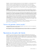
Customer self repair HP products are designed with many Customer Self Repair (CSR) parts to minimize repair time and allow for greater flexibility in performing defective parts replacement. If during the diagnosis period HP (or HP service providers or service partners) identifies that the repair can be accomplished by the use of a CSR part, HP will ship that part directly to you for replacement. There are two categories of CSR parts: • Mandatory—Parts for which customer self repair is mandatory.
Obligatoire - Pièces pour lesquelles la réparation par le client est obligatoire. Si vous demandez à HP de remplacer ces pièces, les coûts de déplacement et main d'œuvre du service vous seront facturés. Facultatif - Pièces pour lesquelles la réparation par le client est facultative. Ces pièces sont également conçues pour permettre au client d'effectuer lui-même la réparation.
In base alla disponibilità e alla località geografica, le parti CSR vengono spedite con consegna entro il giorno lavorativo seguente. La consegna nel giorno stesso o entro quattro ore è offerta con un supplemento di costo solo in alcune zone. In caso di necessità si può richiedere l'assistenza telefonica di un addetto del centro di supporto tecnico HP. Nel materiale fornito con una parte di ricambio CSR, HP specifica se il cliente deve restituire dei componenti.
defekte Teil nicht zurückschicken, kann HP Ihnen das Ersatzteil in Rechnung stellen. Im Falle von Customer Self Repair kommt HP für alle Kosten für die Lieferung und Rücksendung auf und bestimmt den Kurier-/Frachtdienst. Weitere Informationen über das HP Customer Self Repair Programm erhalten Sie von Ihrem Servicepartner vor Ort. Informationen über das CSR-Programm in Nordamerika finden Sie auf der HP Website unter (http://www.hp.com/go/selfrepair).
enviara el componente defectuoso requerido, HP podrá cobrarle por el de sustitución. En el caso de todas sustituciones que lleve a cabo el cliente, HP se hará cargo de todos los gastos de envío y devolución de componentes y escogerá la empresa de transporte que se utilice para dicho servicio. Para obtener más información acerca del programa de Reparaciones del propio cliente de HP, póngase en contacto con su proveedor de servicios local.
Neem contact op met een Service Partner voor meer informatie over het Customer Self Repair programma van HP. Informatie over Service Partners vindt u op de HP website (http://www.hp.com/go/selfrepair). Garantieservice "Parts Only" Het is mogelijk dat de HP garantie alleen de garantieservice "Parts Only" omvat. Volgens de bepalingen van de Parts Only garantieservice zal HP kosteloos vervangende onderdelen ter beschikking stellen.
No caso desse serviço, a substituição de peças CSR é obrigatória. Se desejar que a HP substitua essas peças, serão cobradas as despesas de transporte e mão-de-obra do serviço.
Customer self repair 12
Customer self repair 13
Customer self repair 14
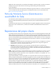
Illustrated parts catalog Mechanical components Item Description Spare part number Customer self repair (on page 5) 1 HP BladeSystem c7000 enclosure — — 2 Rear cage — — 3 Hardware kit 432463-001 Mandatory1 a) Device bay shelf — — b) Vertical cable cover* — — c) Left LCD cap* — — 4 Device bay blank 414051-001 Mandatory1 5 Fan blank 414052-001 Mandatory1 6 Power supply blank 416043-001 Mandatory1 7 Onboard Administrator blank 414054-001 Mandatory1 8 Interconnect blank
Item Description Spare part number Customer self repair (on page 5) b) Right handle cover — — c) Screws for endcaps and handles, rear cage (10) d) Rear cage endcap, top — — — — e) Enclosure bezel ear, right — — f) Enclosure bezel ear, left — — 10 Enclosure right front bezel plastics* ** 709864-001 Mandatory1 11 Enclosure left front bezel plastics* ** 709863-001 Mandatory1 12 Rackmounting kit* 432461-001 Mandatory1 *Not shown. **Platinum models only.
Optional: Opcional— componentes para los que la reparación por parte del usuario es opcional. Estos componentes también están diseñados para que puedan ser reparados por el usuario. Sin embargo, si precisa que HP realice su sustitución, puede o no conllevar costes adicionales, dependiendo del tipo de servicio de garantía correspondiente al producto. 3 No: No—Algunos componentes no están diseñados para que puedan ser reparados por el usuario.
System components Front system components Item Description Spare part number Customer self repair (on page 5) 13 Power supply — — a) HP BladeSystem c7000 power supply 411099-001 Mandatory1 b) HP 2400W High Efficiency power supply* c) HP BL7000 2400W Platinum power supply* d) HP BladeSystem c7000 DC power supply* HP BladeSystem Insight Display 500242-001 Mandatory1 588733-001 Mandatory1 544660-001 Mandatory1 — — a) 7.62 (3.00 in) Insight Display 441203-001 No3 b) 7.62 cm (3.
Item Description Spare part number Customer self repair (on page 5) b) Insight Display LCD pass-thru board (RoHS)* c) Insight Display pass-thru board* ** 519348-001 No3 709866-001 No3 * Not shown ** Platinum models only 1 Mandatory—Parts for which customer self repair is mandatory. If you request HP to replace these parts, you will be charged for the travel and labor costs of this service. 2 Optional—Parts for which customer self repair is optional.
Optional: Optioneel—Onderdelen waarvoor reparatie door de klant optioneel is. Ook deze onderdelen zijn ontworpen voor reparatie door de klant. Als u echter HP verzoekt deze onderdelen voor u te vervangen, kunnen daarvoor extra kosten in rekening worden gebracht, afhankelijk van het type garantieservice voor het product. 3 No: Nee—Sommige HP onderdelen zijn niet ontwikkeld voor reparatie door de klant.
Rear system components Item Description Spare part number Customer self repair (on page 5) 17 Interconnect module (switch) — — a) HP GbE2c Ethernet Blade Switch for HP 414037-001 c-Class BladeSystem b) HP GbE2c Layer 2/3 Ethernet Blade 438475-001 Switch for c-Class BladeSystem* Mandatory1 Mandatory1 c) HP 10Gb Ethernet BL-c Switch* 447116-001 Mandatory1 d) HP 1:10Gb Ethernet BL-c Switch* 438476-001 Mandatory1 e) Brocade 4Gb SAN Switch for HP c-Class 411120-001 BladeSystem, 12 ports* Mandat
Item 18 19 20 Description Spare part number Customer self repair (on page 5) g) Brocade 4Gb SAN Switch for HP c-Class BladeSystem, 24 ports, with Power Pack Software* h) Cisco Catalyst Blade Switch 3020 for HP c-Class BladeSystem* i) HP 1/10Gb Virtual Connect Ethernet Module for c-Class BladeSystem* j) HP 4Gb Virtual Connect Fibre Channel Module for c-Class BladeSystem* k) HP 4X DDR IB Switch Module for HP c-Class BladeSystem* l) HP BLc 1/10GB-F Virtual Connect Enet Module* m) Cisco MDS 9124e 12-port
Item Description Spare part number Customer self repair (on page 5) b) Onboard Administrator tray (RoHS)* 519346-001 Mandatory1 21 Active Cool 200 fan 413996-001 Mandatory1 22 Midplane assembly — — a) Midplane assembly 414050-001 No3 b) Midplane assembly (RoHS)* 519345-001 No3 c) Midplane assembly, AMP* ** (includes 689229-001 the rear cage) Insight Display connector board No3 — a) Insight Display connector board 416001-001 No3 b) Insight Display LCD connector board (RoHS)* AC modu
No: Non—Certaines pièces HP ne sont pas conçues pour permettre au client d'effectuer lui-même la réparation. Pour que la garantie puisse s'appliquer, HP exige que le remplacement de la pièce soit effectué par un Mainteneur Agréé. Ces pièces sont identifiées par la mention “Non” dans le Catalogue illustré. 3 Mandatory: Obbligatorie—Parti che devono essere necessariamente riparate dal cliente.
Illustrated parts catalog 25
Removal and replacement procedures Required tools The following items are required for some procedures: • T-10 Torx screwdriver • T-15 Torx screwdriver Safety considerations Before performing service procedures, review all the safety information. Preventing electrostatic discharge To prevent damaging the system, be aware of the precautions you need to follow when setting up the system or handling parts.
WARNING: To reduce the risk of personal injury or equipment damage when unloading a rack: • At least two people are needed to safely unload the rack from the pallet. An empty 42U rack can weigh as much as 115 kg (253 lb), can stand more than 2.1 m (7 ft) tall, and might become unstable when being moved on its casters. • Never stand in front of the rack when it is rolling down the ramp from the pallet. Always handle the rack from both sides. WARNING: The enclosure is very heavy.
WARNING: To reduce the risk of personal injury from hot surfaces, allow the drives and the internal system components to cool before touching them. WARNING: To reduce the risk of electric shock or damage to the equipment, enter enclosures or perform service on system components only as instructed in the user documentation. WARNING: A risk of electric shock from high leakage current exists.
This method forces the server blades or workstation blades to enter standby mode without properly exiting applications and the OS. It provides an emergency shutdown method if an application stops responding. • Execute one of the following commands using the Onboard Administrator CLI: poweroff server [bay number] or poweroff server [bay number] force The first command initiates a controlled shutdown of applications and the OS before the server blades or workstation blades enters standby mode.
HP BladeSystem c7000 power supply or power supply blank CAUTION: This procedure provides instructions for replacement of a failed part only. To change the configuration of components, see the appropriate HP BladeSystem c-Class enclosure setup and installation guide. CAUTION: Do not mix HP 2250W, HP 2400W High Efficiency, HP BL7000 2400W Platinum, or -48vDC power supplies in one enclosure. Install only one type of power supply in a single enclosure.
Device bay blank Remove the blank from the enclosure: CAUTION: For best cooling practices, do not operate the enclosure for extended periods with more than one component or blank removed. When removing an active component, replace it with a blank. To replace the component, reverse the removal procedure. Device bay shelf The c7000 enclosure is divided into four quadrants by the vertical support metal work. Within each quadrant, a removable divider supports half-height blades.
Item Description 1 Blade Zone 1 2 Blade Zone 2 3 Blade Zone 3 4 Blade Zone 4 Storage blades and tape blades can be installed in the same quadrant as both full-height and half-height blades. A bracket ships with each SB40c Storage Blade that allows a half-height blade to be mounted on top of the storage blade. The lower tape or storage blade cannot be removed without first removing the upper half-height blade. To remove the component: 1.
2. Slide the device bay shelf locking tab to the left to open it. 3. Push the device bay shelf back until it stops, lift the right side slightly to disengage the two tabs from the divider wall, and then rotate the right edge downward (clockwise).
4. Lift the left side of the device bay shelf to disengage the three tabs from the divider wall, and then remove it from the enclosure. To replace the component, reverse the removal procedure. Half-height or full-height blade CAUTION: This procedure provides instructions for replacement of a failed part only. To change the configuration of components, see the appropriate HP BladeSystem c-Class enclosure setup and installation guide.
Item Description 1 Blade Zone 1 2 Blade Zone 2 3 Blade Zone 3 4 Blade Zone 4 Storage blades and tape blades can be installed in the same quadrant as both full-height and half-height blades. A bracket ships with each SB40c Storage Blade that allows a half-height blade to be mounted on top of the storage blade. The lower tape or storage blade cannot be removed without first removing the upper half-height blade. To remove the component: 1.
o Half-height blade o Full-height blade CAUTION: For best cooling practices, do not operate the enclosure for extended periods with more than one component or blank removed. When removing an active component, replace it with a blank. To replace the component, reverse the removal procedure. HP BladeSystem Insight Display To remove the component: 1. Power down the enclosure (on page 29). 2.
o Full-height blades: bays 1-5 ("Half-height or full-height blade" on page 34) o Device bay blanks: bays 9-13 ("Device bay blank" on page 31) o Power supplies or blanks: bays 1-4 ("HP BladeSystem c7000 power supply or power supply blank" on page 30) 3. Remove the three T-15 Torx screws that secure the Insight Display cable center cover, and then remove the cover. 4. Disconnect the Insight Display cable. 5. Remove the two T-10 Torx screws that secure the Insight Display. 6.
8. Carefully remove the Insight Display cable through the cable channel. To replace the component, reverse the removal procedure. Fan blank To remove the component: 1. Turn the handle counterclockwise. 2. Remove the blank. CAUTION: For best cooling practices, do not operate the enclosure for extended periods with more than one component or blank removed. When removing an active component, replace it with a blank. To replace the component, reverse the removal procedure.
Active Cool 200 fan CAUTION: This procedure provides instructions for replacement of a failed part only. To change the configuration of components, see the appropriate HP BladeSystem c-Class enclosure setup and installation guide. To remove the component: 1. Turn the handle counterclockwise. 2. Remove the fan. CAUTION: For best cooling practices, do not operate the enclosure for extended periods with more than one component or blank removed. When removing an active component, replace it with a blank.
2. Remove the blank. CAUTION: For best cooling practices, do not operate the enclosure for extended periods with more than one component or blank removed. When removing an active component, replace it with a blank. To replace the component, slide the component into the bay until it locks into place. Enclosure front bezels (Platinum models only) Remove the component as indicated. To replace the component, reverse the removal procedure.
CAUTION: This procedure provides instructions for replacement of a failed part only. To change the configuration of components, see the appropriate HP BladeSystem c-Class enclosure setup and installation guide. To remove the component: CAUTION: To prevent data loss, redirect network activity or be sure that all critical network activity has stopped before removing the interconnect module. IMPORTANT: An SFP port must be occupied by an SFP transceiver or an SFP dust cover at all times. 1.
4. Remove the interconnect bay divider. To replace the component, reverse the removal procedure. Onboard Administrator blank Remove the component as indicated. CAUTION: For best cooling practices, do not operate the enclosure for extended periods with more than one component or blank removed. When removing an active component, replace it with a blank. To replace the component, reverse the removal procedure.
Onboard Administrator To remove the component: 1. Disconnect all cables from the component. 2. Press the release tab and open the handle. 3. Remove the Onboard Administrator module. CAUTION: For best cooling practices, do not operate the enclosure for extended periods with more than one component or blank removed. When removing an active component, replace it with a blank. To replace the component, reverse the removal procedure. Onboard Administrator tray To remove the component: 1.
4. Remove the Onboard Administrator tray. CAUTION: For best cooling practices, do not operate the enclosure for extended periods with more than one component or blank removed. When removing an active component, replace it with a blank. To replace the component, reverse the removal procedure. AC input module To remove the component: 1. Power down the server blades ("Power down the server blades or workstation blades" on page 28). 2. Power down the enclosure (on page 29). 3.
5. Configure the AC input module. For more information, see "Midplane assembly (on page 53)." To replace the component, reverse the removal procedure. AC control module To remove the component: 1. Disconnect all USB connections from the Onboard Administrator to the control module. 2. Loosen the two slotted screws that secure the control module. 3. Remove the control module. To replace the component, reverse the removal procedure.
o Power supplies ("HP BladeSystem c7000 power supply or power supply blank" on page 30) 5. Remove the fans ("Active Cool 200 fan" on page 39). 6. Remove the interconnect switches and Pass-Thru modules ("Interconnect switch or Pass-Thru module" on page 40). 7. Remove the Onboard Administrator modules ("Onboard Administrator" on page 43). 8. Remove the Onboard Administrator tray ("Onboard Administrator tray" on page 43). 9. Remove the rear cage. a.
CAUTION: When removing and lifting the rear cage, always grasp the handholds as far forward as possible. The front end of the rear cage is heavy and the handholds provide a more balanced location to distribute the weight of the cage during lifting. CAUTION: When removing the rear cage and midplane assembly, the connectors on the midplane assembly are susceptible to damage. Use caution to avoid damage to the pins and connectors. e. Use the handholds to extend and remove the rear cage from the enclosure.
11. Remove the rear cage ("Rear cage" on page 45). WARNING: To reduce the risk of personal injury or equipment damage, at least two people are needed to safely move the rear cage. 12. Remove the three T-15 Torx screws that secure the Insight Display cable center cover, and then remove the cover. 13. Disconnect the Insight Display cable. 14. Remove the four T-15 Torx screws that secure the interconnect board cover, and then remove the cover. NOTE: The device bay walls have been removed for clarity.
15. Remove the two slotted T-15 Torx screws that secure the interconnect board. 16. Remove the interconnect board. To replace the component, reverse the removal procedure. Insight Display signal pass-thru board WARNING: To reduce the risk of damage to the midplane and component connectors, always remove or disengage and extend all blades and power supplies approximately 8 cm (3 in) before removing or installing the rear cage. To remove the component: 1.
4. Disengage and extend the following components approximately 8 cm (3 in): o Half-height and full-height blades ("Half-height or full-height blade" on page 34) o Power supplies ("HP BladeSystem c7000 power supply or power supply blank" on page 30) 5. Remove the fans ("Active Cool 200 fan" on page 39). 6. Remove the interconnect switches and Pass-Thru modules ("Interconnect switch or Pass-Thru module" on page 40). 7. Remove the Onboard Administrator modules ("Onboard Administrator" on page 43).
10. Disconnect the pass-thru board from the cable. To replace the component, reverse the removal procedure. Location discovery services board (Platinum models only) To remove the component: 1. Power down the server blades ("Power down the server blades or workstation blades" on page 28). 2. Power down the enclosure (on page 29). 3. Remove the handle cover.
4. Remove the location discovery services board cover. 5. Disconnect the cable from the location discovery services board.
6. Remove the screw, lift up on the board, and then remove the board. To replace the component, reverse the removal procedure. Midplane assembly Before replacing the midplane, locate and record the enclosure serial number and part number, using one of the following methods: • Locate the enclosure tag on the front, side, or rear of the enclosure. • Access the Onboard Administrator. • Log in to the Onboard Administrator CLI and run the command Show Enclosure Info.
2. Power down the enclosure (on page 29). NOTE: Be sure to note the location of each removed component so it can be returned to its original location after the midplane assembly is replaced. 3. Disconnect all cables from the enclosure. 4.
11. Remove the eight slotted T-15 Torx screws that secure the midplane assembly, and then remove the midplane assembly from the rear cage. To replace the midplane assembly, reverse the removal procedure. CAUTION: The LCD cable must be correctly routed for proper operation. To route the LCD cable: 1. When installing the midplane assembly onto the rear cage assembly, ensure the LCD cable is routed behind the interconnect module rubber boot and through the sheet-metal gaps.
2. Route the cable between the Insight Display signal pass-thru board pin guide and the screw mounts. Be careful not to pinch the cable between the Insight Display signal pass-thru board and the screw mount as shown in the following figure. 3. Place the Insight Display signal pass-thru board properly over the guide pin and the screw mount and screw the Insight Display signal pass-thru board to the rear cage assembly.
o 4—DC power o 5—Single Phase Intelligent PDU 7. Install all VC Ethernet modules, VC-FC modules, and all other interconnect modules in the same bay they were removed from. 8. Reconnect all cables to those modules to the same ports they were removed from. 9. Wait two minutes. 10. Install all the server blades into the same bays they were removed from.
Cabling Single-phase AC configuration Three-phase AC configuration Cabling 58
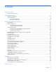
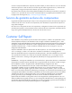
HP BladeSystem c7000 Enclosure DC configuration Item Description 1 Chassis grounding lugs 2 DC connectors for power supply bay 1 3 DC connectors for power supply bay 2 4 DC connectors for power supply bay 3 5 DC connectors for power supply bay 4 6 DC connectors for power supply bay 5 7 DC connectors for power supply bay 6 8 Chassis grounding lugs 9 -48 VDC power connections 10 DC return power connections Cabling 59
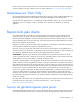
Onboard Administrator cabling Item Connector Description 1 OA/iLO Ethernet 1000BaseT RJ45 connector, which provides Ethernet access to the Onboard Administrator and the iLO on each server blades or workstation blades. Also supports interconnect modules with management processors configured to use the enclosure management network. Autonegotiates 1000/100/10 or can be configured to force 100Mb or 10Mb full duplex. 2 USB USB 2.
Onboard Administrator with KVM cabling Item Connector Description 1 OA/iLO Ethernet 1000BaseT RJ45 connector, which provides Ethernet access to the Onboard Administrator and the iLO on each server blades or workstation blades. Also supports interconnect modules with management processors configured to use the enclosure management network. Autonegotiates 1000/100/10 or can be configured to force 100Mb or 10Mb full duplex. 2 USB USB 2.
Diagnostic tools Troubleshooting resources The HP BladeSystem c-Class Enclosure Troubleshooting Guide provides procedures and solutions for troubleshooting HP BladeSystem c-Class enclosures. This guide explains how to use the Insight Display to troubleshoot enclosures, and it includes a flowchart to help you navigate the troubleshooting process. To view the guide, see the HP website (http://www.hp.com/support/BladeSystem_Enclosure_TSG_en).
HP Insight Diagnostics survey functionality HP Insight Diagnostics (on page 62) provides survey functionality that gathers critical hardware and software information on ProLiant server blades or workstation bladess. This functionality supports operating systems that may not be supported by the server blades or workstation blades. For operating systems supported by the server blades or workstation blades, see the HP website (http://www.hp.com/go/supportos).
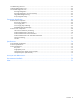
Component identification Enclosure front components Item Description 1 Device bays* 2 Air intake slot (Do not block.) 3 Power supply bay 1 4 Power supply bay 2 5 Power supply bay 3 6 Power supply bay 4 7 Insight Display 8 Power supply bay 5 9 Power supply bay 6 10 Air intake slot (Do not block.) *For more information, see "Device bay numbering (on page 64)." Device bay numbering Each enclosure requires interconnects to provide network access for data transfer.
IMPORTANT: When looking at the rear of the enclosure, front device bay numbering is reversed.
Power supply LEDs Power LED 1 (green) Fault LED 2 (amber) Condition Off Off No AC power to the power supply On Off Normal Off On Power supply failure Power supply bay numbering Component identification 66
HP BladeSystem Insight Display Insight Display overview The Insight Display enables the rack technician to configure the enclosure initially. It also provides information about the health and operation of the enclosure. See the HP BladeSystem Onboard Administrator User Guide for additional information. The Insight Display background color varies with the condition of the enclosure health: • Blue—The Insight Display background illuminates blue when the enclosure UID is active.
HP BladeSystem Insight Display components Item Description Function 1 Insight Display screen Displays Main Menu error messages and instructions 2 Left arrow button Moves the menu or navigation bar selection left one position 3 Right arrow button Moves the menu or navigation bar selection right one position 4 OK button Accepts the highlighted selection and navigates to the selected menu 5 Down arrow button Moves the menu selection down one position 6 Up arrow button Moves the menu select
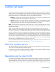
Item Description 1 Fan bay 1 2 Fan bay 2 3 Fan bay 3 4 Fan bay 4 5 Fan bay 5 6 Interconnect bay 2 7 Interconnect bay 4 8 Interconnect bay 6 9 Interconnect bay 8 10 Onboard Administrator bay 2 11 Power supply exhaust vent (do not block) 12 Fan bay 10 13 Fan bay 9 14 Fan bay 8 15 Fan bay 7 16 Fan bay 6 17 AC power connectors 18 Onboard Administrator bay 1 19 Interconnect bay 7 20 Interconnect bay 5 21 Interconnect bay 3 22 Interconnect bay 1 Interconnect module ba
Server blade signal Interconnect bay number NICs 1, 2, 3, and 4 (embedded) 1, 2 Mezzanine 1 3, 4 Mezzanine 2 5, 6 and then 7, 8 Mezzanine 3 7, 8 and then 5, 6 Interconnect bay label NOTE: For information on the location of LEDs and ports on individual interconnect modules, see the documentation that ships with the interconnect module.
Onboard Administrator LEDs and buttons Item Description 1 Onboard Administrator UID LED 2 Enclosure UID LED and UID button 3 Onboard Administrator active LED 4 Onboard Administrator health LED 5 Onboard Administrator reset button Onboard Administrator with KVM LEDs and buttons Item Description 1 Onboard Administrator UID LED Component identification 71
Item Description 2 Enclosure UID LED and UID button 3 Onboard Administrator health LED 4 Onboard Administrator active LED 5 Onboard Administrator reset button Fan bay numbering Fan LED LED color Fan status Solid green The fan is working. Solid amber The fan has failed.
LED color Fan status Flashing amber See the Insight Display screen.
Specifications Environmental specifications Specification Value Temperature range* Operating 10°C to 35°C (50°F to 95°F) Non-operating -30°C to 60°C (-22°F to 140°F) Wet bulb temperature Operating 28ºC (82.4ºF) 38.7ºC (101.7ºF) Non-operating Relative humidity (noncondensing)** Operating 20% to 80% Non-operating 5% to 95% * All temperature ratings shown are for sea level. An altitude derating of 1°C per 304.8 m (1.8°F per 1000 ft) to 3048 m (10,000 ft) is applicable. No direct sunlight allowed.
Specification Value Unboxed 68.0 kg (150.0 lb) Shipping 87.5 kg (193.0 lb) Maximum enclosure weight Unboxed 204.0 kg (450.0 lb) Shipping 223.6 kg (493.0 lb) * No components installed.
Three-phase power (North America/Japan) Specification HP BladeSystem HP 2400W High HP BL7000 2400W c7000 Power Supply Efficiency Power Supply Platinum Power Supply Power cords (2) NEMA L15-30p 2.44 m NEMA L15-30p 2.44 m (10 ft) (10 ft) NEMA L15-30p 2.
Acronyms and abbreviations ADU Array Diagnostics Utility CSR Customer Self Repair ESD electrostatic discharge HVDC High Voltage DC iLO Integrated Lights-Out IML Integrated Management Log OA Onboard Administrator SFP small form-factor pluggable SIM Systems Insight Manager Acronyms and abbreviations 77
Documentation feedback HP is committed to providing documentation that meets your needs. To help us improve the documentation, send any errors, suggestions, or comments to Documentation Feedback (mailto:docsfeedback@hp.com). Include the document title and part number, version number, or the URL when submitting your feedback.
Index A E AC input module 44 AC power configuration, single-phase 58 AC power configuration, three-phase 58 AC power configurations 58 ADU (Array Diagnostic Utility) 63 Array Diagnostic Utility (ADU) 63 electrostatic discharge 26 enclosure LEDs 64 enclosure specifications 74 enclosure, configuring 67 environmental specifications 74 B bay numbering, interconnect 69 bay numbering, power supply 66 buttons 26, 64 C cable configuration 60 cable, routing 53 cables 58 cabling 53, 58, 60 cabling, Onboard Admin
L system components 18, 64 LCD 53 LEDs, fan 72 LEDs, unit identification (UID) 67, 71 location discovery services board 51 T M U management module 45 management tools 62 mechanical components 15 midplane assembly 53 midplane assembly replacement 53 UID LED 67, 71 utilities 62 O three-phase AC configuration 58 troubleshooting resources 62 W warnings 26 warranty 5 Onboard Administrator 43, 62 Onboard Administrator blank 42 Onboard Administrator components 70 Onboard Administrator module, cabling 60