HP BladeSystem c7000 Enclosure Quick Setup Instructions Part Number 411762-403
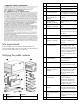
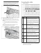
Site requirements Item Name Description 2 Rear cage The rear section of the enclosure 3 Device bay blank A mandatory insert installed in any unused device bay 4 Power supply blank A mandatory insert installed in any unused power supply bay 5 Enclosure hot-plug power The power supply for the supply (quantity as enclosure ordered) 6 Full-height device (quantity as ordered) The full-height server or storage blade 7 Half-height device (quantity as ordered) The half-height server or storage b
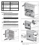
Item Name Description documentation on using the enclosure 19* Hard copy installation instructions for blades, options, and interconnects The printed installation instructions 20* Installation checklist A checklist to guide you through installation of the enclosure and components * Not shown Installing the enclosure WARNING: Because the fully-populated enclosure can weigh up to 217.
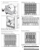
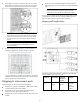
4. Half-height device bay numbering Install the rear cage into the enclosure, close the hinges, and tighten the thumbscrews. Power supply bay numbering Enclosure bay identification Fan bay numbering Before installing front or rear components into the enclosure, review enclosure bay numbering for each component.
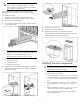
CAUTION: Do not mix HP 2250W, HP 2400W High Efficiency, HP BL7000 2400W Platinum, or -48vDC power supplies in one enclosure. Install only one type of power supply in a single enclosure. If your HP BladeSystem c7000 Enclosure is equipped with a three-phase power configuration, you need six power supplies. To install a power supply: 1. To gain access to all power supply bays, slide the HP BladeSystem Insight Display to the right or left as needed. 2. Remove the power supply blank. 3.
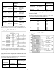
Connecting the cables NOTE: When installing a fan in the top row of fan bays, orient the fan so that the LED is in the lower right corner. When installing a fan in the bottom row of fan bays, orient the fan so the LED is in the upper left corner. 1. Identify all connectors. Item Connector Description 2. Install fan blanks in any unused fan bays. 3.
3. If more than one enclosure is installed in the rack, use a CAT5 patch cable to connect the enclosure link-down port on the upper enclosure to the enclosure link-up port on the lower enclosure. • Gen8 servers have FlexibleLOM adapters that have the same port mapping as the previous generation server blade Embedded NICs. NOTE: 1x and 2x port mezzanine cards interface with single-wide interconnect modules. 4x port mezzanine cards interface with double-wide interconnect modules.
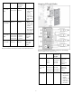
Connection Port number Connects to interconnect bay/port Mezzanine slot 1x/2x port 1 3/Port N 1—1x or 2x 1x/2x port 2 4/Port N cards Mezzanine slot 4x port 1 1—4x cards 3/Port N Mezzanine slot 1x/2x port 1 5 / port N 2—1x or 2x 1x/2x port 2 6 / port N cards 1x/2x port 3 7 / port N 1x/2x port 4 8 / port N Mezzanine slot 4x port 1 2—4x cards 4x port 2 5/Port N 7/Port N Mapping full-height blades Comments • One single-wide interconnect module • Four port cards will only connect the first two ports
Connection Port number Connects to interconnect bay/port Mezzanine slot 1x/2x port 1 5/Port N 2—1x or 2x 1x/2x port 2 6/Port N cards 1x/2x port 3 7/Port N Up to four single-wide interconnect modules 1x/2x port 4 8/Port N Mezzanine slot 4x port 1 2—4x cards 4x port 2 5/Port N One or two double-wide interconnect modules 7/Port N Mezzanine slot 1x/2x port 1 7/Port N+8 3—1x or 2x 1x/2x port 2 8/Port N+8 cards 1x/2x port 3 5/Port N+8 1x/2x port 4 6/Port N+8 Mezzanine slot 4x port 1 3—4x cards 4x port 2
• Interconnect bay crosslinks B side Interconnect bay crosslinks are wired between adjacent interconnect bay pairs. To support network connections for specific signals, install an interconnect module in the bay corresponding to the embedded NIC or mezzanine signals. You can enable these signals to provide module-to-module connections, such as Ethernet crosslink ports between matching switches, or Virtual Connect modules as stacking links.
double-wide interconnect modules. To remove an interconnect bay divider, press the release tab, and pull the interconnect bay divider out of the enclosure. o On the right side: To install the power cord retention bracket on the right side of the enclosure, ensure the power cord retention tabs are located on the left side of the snap clamps. 2. Install interconnect blanks in any unused interconnect bays. 7. 3.
Three-phase power configuration 9. Select Accept All at the bottom of the Enclosure Settings, and then press OK to accept all the settings to continue. If you are setting up a single enclosure, proceed to step 11. 10. Select Accept, and then press OK to apply the Enclosure Settings (Redundancy Mode, Limit AC, Power Savings, Rack Name, and Insight Display PIN) to other linked enclosures. 11. Follow the instructions on the Check: Installation & Cables screen, and then select Continue.
12. Follow the instructions on the Blades Powering Up screen, and then select Main Menu. e. Follow the on-screen prompts to finish the installation. (To update the firmware and systems software, an Internet connection is required.) • Remote deployment installation—Use Insight Control server deployment for an automated solution to remotely deploy an operating system. For additional system software and firmware updates, download the HP Service Pack for ProLiant (SPP) from the HP website (http://www.hp.
Documentation feedback HP is committed to providing documentation that meets your needs. To help us improve the documentation, send any errors, suggestions, or comments to Documentation Feedback (mailto:docsfeedback@hp.com). Include the document title and part number, version number, or the URL when submitting your feedback.
© Copyright 2006, 2013 Hewlett-Packard Development Company, L.P. The information contained herein is subject to change without notice. The only warranties for HP products and services are set forth in the express warranty statements accompanying such products and services. Nothing herein should be construed as constituting an additional warranty. HP shall not be liable for technical or editorial errors or omissions contained herein.