Installation Instructions: HP Universal Rack Mount Kit for hp Carrier-Grade Servers cc2300, cc3300, and cc3310 (19-23 inch 2- and 4-Post Racks) Version 2.0 Manufacturing Part Number: cc3310_RackMount February 2004 U.S.A. © 2003-2004 Hewlett-Packard Development Company, L.P.
Legal Notices Copyright ã 2003-2004 Hewlett-Packard Development Company, L.P. The information contained herein is subject to change without notice. The only warranties for HP products and services are set forth in the express warranty statements accompanying such products and services. Nothing herein should be construed as constituting an additional warranty. HP shall not be liable for technical or editorial errors or omissions contained herein. Printed in the U.S.A. Related Documents.
HP Universal Rack Mount Kit (with Stop Feature) for 19-23 in.
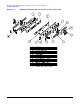
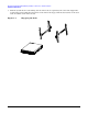
HP Universal Rack Mount Kit (with Stop Feature) for 19-23 in. 2- and 4-Post Racks Installation Instructions Figure 1-1.
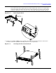
HP Universal Rack Mount Kit (with Stop Feature) for 19-23 in. 2- and 4-Post Racks Installation Instructions Figure 1-2.
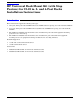
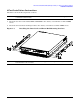
HP Universal Rack Mount Kit (with Stop Feature) for 19-23 in. 2- and 4-Post Racks Installation Instructions 4-Post Installation Instructions Install the rack mount kit components as follows: NOTE Although a cc3300 chassis is shown in the illustrations, these instructions also apply to a cc3310 and cc2300 chassis. 1. Attach the two inner rails (marked LEFT and RIGHT) to the chassis, each with three 8-32x1/4" SEMS screws. 2.
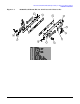
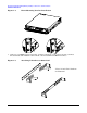
HP Universal Rack Mount Kit (with Stop Feature) for 19-23 in. 2- and 4-Post Racks Installation Instructions Figure 1-4. Front Mounting Bracket Installation 3. Using two 8-32 KEPS nuts per L-bracket, assemble L-brackets* to the outer rail’s four outermost threaded studs. (The A6945A rack mount kit contains both EIA and ETSI L-brackets.) Figure 1-5. Attaching L-Brackets to Outer Rail *Note: 23-inch EIA L-brackets are illustrated.
HP Universal Rack Mount Kit (with Stop Feature) for 19-23 in. 2- and 4-Post Racks Installation Instructions 4. Install the outer rail subassemblies into the rack using ten or twelve (19" or 23" kits, respectively) 1032x1/2" SEMS screws. If bar-nuts are used, they should be installed such that all threads are aligned vertically, ensuring the center hole is not skewed with respect to the holes on the rack rail.
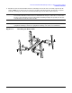
HP Universal Rack Mount Kit (with Stop Feature) for 19-23 in. 2- and 4-Post Racks Installation Instructions 5. Slide the system into the rack making sure the inner rails are captured by the outer rails. Support the weight of the system until the lock features on the inner rails engage with the slot features on the outer rails. An audible “click” will be heard. Figure 1-7.
HP Universal Rack Mount Kit (with Stop Feature) for 19-23 in. 2- and 4-Post Racks Installation Instructions NOTE Figure 1-8. Once engaged, the lock features must be released to remove the system from the rack. To release the lock features, depress the two latches with the blue arrows (one on either side) downward. While depressing the lock features and supporting the system weight, pull the system out. Pressure can be released once the lock features disengage from the outer rail. Releasing the Rails 6.
HP Universal Rack Mount Kit (with Stop Feature) for 19-23 in. 2- and 4-Post Racks Installation Instructions NOTE If installing into a 19-inch 4-post rack that has EIA wide hole spacing, the EIA wide adapter bracket must be used. Install this bracket onto the face of the L-brackets using the same 1032x1/2" SEMS screws that fasten the L-brackets to the rack’s front equipment mounting rails. Figure 1-10.
HP Universal Rack Mount Kit (with Stop Feature) for 19-23 in. 2- and 4-Post Racks Installation Instructions 2-Post Installation Instructions Install the rack mount kit components as follows: NOTE Although a cc3300 chassis is shown in the illustrations, these instructions also apply to a cc3310 and cc2300 chassis. 1. Attach the two inner rails (marked LEFT and RIGHT) to the chassis, each with three 8-32x1/4" SEMS screws. 2.
HP Universal Rack Mount Kit (with Stop Feature) for 19-23 in. 2- and 4-Post Racks Installation Instructions NOTE The universal front mounting bracket can be flipped in order to locate the system further forward in the rack (see inset). Figure 1-12. Front Mounting Brackets 3. Using three 8-32 KEPS nuts per L-bracket, assemble the appropriate L-brackets* and the 2-post mounting bracket to the outer rail. (A6945A contains both EIA and ETSI L-brackets.
HP Universal Rack Mount Kit (with Stop Feature) for 19-23 in. 2- and 4-Post Racks Installation Instructions 4. Install the two outer rail subassemblies in the rack using twelve 10-32x1/2" SEMS screws or other appropriate fasteners. If bar-nuts are used, they should be installed such that all threads are aligned vertically, ensuring the center hole is not skewed with respect to the holes on the rack rail.
HP Universal Rack Mount Kit (with Stop Feature) for 19-23 in. 2- and 4-Post Racks Installation Instructions 5. Slide the system into the rack making sure the inner rails are captured by the outer rails. Support the weight of the system until lock features on the inner rails engage with the slot features on the outer rails. An audible “click” will be heard. Figure 1-15. NOTE Engaging the Rails Once engaged, the lock features must be released to remove the system from the rack.
HP Universal Rack Mount Kit (with Stop Feature) for 19-23 in. 2- and 4-Post Racks Installation Instructions 6. Install two 10-32X1/2" SEMS screws to hold the universal front mounting bracket to the 2-post mounting bracket. Figure 1-17.