
Workgroup System and Cluster Platform Express Overview and Hardware Installation Guide

E Configuration Rules for CPE BladeSystems
This appendix provides the configuration and power distribution rules for CPE BladeSystem
configurations. The following sections discuss:
• CP Workgroup System device and interconnect bays (see Section E.1)
• CP Workgroup System fan bays (see Section E.2)
• CP Workgroup System power and configuration rules (see Section E.3)
• CPE with BladeSystem c7000 enclosure device and interconnect module bay rules (see
Section E.4)
• CPE with BladeSystem c7000 enclosure fan bay rules (see Section E.5)
• CPE with BladeSystem c7000 enclosure power distribution rules (see Section E.6)
E.1 CP Workgroup System Device and Interconnect Bays
Section E.1 and Section E.1.2 summarize the use of the device bays and interconnect bays for
c3000 enclosures in CP Workgroup System configurations.
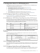
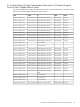
E.1.1 HP BladeSystem c3000 Enclosure Device Bays (Front of the c3000 Enclosure)
The following table provides the HP BladeSystem c3000 enclosure's device bay rules for CP
Workgroup System. If the control node is a server blade, it is installed in device bay 5. Otherwise,
device bay 5 is used for a compute node. If the control node is a server blade and a storage blade
is also required, the storage blade is installed in device bay 6.
UseBayUseBay
Server Blade8Server Blade4
Server Blade7Server Blade3
Storage Blade (SB40c) or Server Blade6Server Blade2
Control Node/Server Blade5Server Blade1
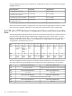
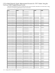
E.1.2 HP BladeSystem c3000 Enclosure Interconnect Bays (Rear of the c3000
Enclosure)
The following table provides the HP BladeSystem c3000 enclosure's interconnect module bay
rules for CPE Workgroup systems.
Interconnect Module Bay 2Interconnect Module Bay 1Bay
Not UsedHP GbE2c ModuleUse
Interconnect Module Bay 4Interconnect Module Bay 3Bay
InfiniBand Switch Module (double-width)Use
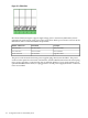
E.2 CP Workgroup System Fan Bays
If more than half of the device bays are populated (for example, there are more than four server
blades) the enclosure is configured with six fans. Otherwise, the enclosure is configured with
four fans.
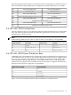
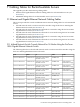
E.3 CP Workgroup System Power and Configuration Rules
To meet the power requirements, CPE c3000 configurations use two single-phase PDUs as shown
in the following table. An additional power strip is required for the control node and TFT. A
E.1 CP Workgroup System Device and Interconnect Bays 111