
Workgroup System and Cluster Platform Express Overview and Hardware Installation Guide
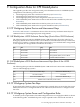
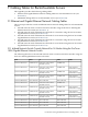

The following table summarizes the use of the interconnect module bays for c7000 enclosures in
HP Cluster Platform Express BladeSystem configurations with double-density server blades.
Interconnect Module Bay 2Interconnect Module Bay 1Bay
HP GbE2c ModuleHP GbE2c ModuleUse
Interconnect Module Bay 4Interconnect Module Bay 3Bay
Not usedOptional HP GbE2c Module (for external network)Use
Interconnect Module Bay 6Interconnect Module Bay 5Bay
InfiniBand Switch Module (double-width)Use
Interconnect Module Bay 8Interconnect Module Bay 7Bay
InfiniBand Switch Module (double-width)Use
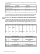
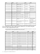
E.5 CPE with c7000 Fan Bay Rules
Fan bays and devices bays are populated according the CPE with c7000 enclosure configuration
rules. The following table shows both fan and device population rules. Device bays are to be
populated in the sequence shown.
Note:
In the following table, the term “device” refers to either a server blade or a storage blade.
Fan BaysNumber of FansDevice BaysNumber of Devices
4, 5, 9, 1041 and 21-2
3, 4, 5, 8, 9, 1061, 2, 3, 4, 9, 10, 11, 123-7
1, 2, 4, 5, 6, 7, 9, 1081-168-16
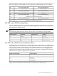
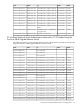
E.6 CPE with c7000 Power Distribution Rules
CPE BladeSystem with c7000 enclosure configurations support redundant power supplies (N+1)
in the c7000 enclosure. In order to meet power requirements, each enclosure is configured with
up to five power supplies. The number of power supplies required for a configuration might
vary depending on the type and quantity of server blades in the enclosure. The appropriate
number of power supplies will be installed in each enclosure prior to shipment. The following
table shows how the power supply bays are populated:
Power Supply BaysNumber of Power Supplies
1, 41 + 1
1, 2 and 42 + 1
1, 2, 4 and 53 + 1
1, 2, 3, 4 and 54 + 1
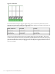
Figure E-1 shows the number, and the location of the PSUs in a c7000 enclosure.
E.5 CPE with c7000 Fan Bay Rules 113