
Workgroup System and Cluster Platform Express Overview and Hardware Installation Guide
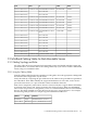
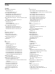


CableLabelToLabelFrom
C7533AServer06-MPEmbedded MP in Node 06Consol-ES1-P34ProCurve 2650 Port 34
Not connectedProCurve 2650 Port 35
Not connectedProCurve 2650 Port 36
C7533AServer05-MPEmbedded MP in Node 05Consol-ES1-P37ProCurve 2650 Port 37
C7533AServer04-MPEmbedded MP in Node 04Consol-ES1-P38ProCurve 2650 Port 38
C7533AServer03-MPEmbedded MP in Node 03Consol-ES1-P39ProCurve 2650 Port 39
C7533AServer02-MPEmbedded MP in Node 02Consol-ES1-P40ProCurve 2650 Port 40
C7533AServer01-MPEmbedded MP in Node 01Consol-ES1-P41ProCurve 2650 Port 41
C7533AControl-MPEmbedded MP in Control
Node
Consol-ES1-P42ProCurve 2650 Port 42
Not connectedProCurve 2650 Port 43
Not connectedProCurve 2650 Port 44
Not connectedProCurve 2650 Port 45
Not connectedProCurve 2650 Port 46
Not connectedProCurve 2650 Port 47
Not connectedProCurve 2650 Port 48
Not connectedProCurve 2650 Port 49
C7533AAdmin-ES1-P48Uplink to Admin switchConsol-ES1-P50ProCurve 2650 Port 50
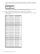
F.2 InfiniBand Cabling Tables for Rack-Mountable Servers
F.2.1 Cabling Topology and Rules
All of the cables in factory-integrated rack-mounted systems are labeled with their origin and
port destinations. You need to refer to the cabling tables only if you need to recable a dismantled
cluster using new, unlabeled cables.
F.2.1.1 Using the Cabling Tables
From the cabling tables listed in the appendices of this guide, select the appropriate cabling table
that matches the configuration of your cluster.
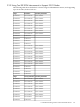
Verify the tables by comparing the port addresses in the tables to the port addresses printed on
the cable labels. These labels identify the origin and destination of each cable, such as from a
port in the interconnect, to a port in the HCA that is installed in the node.
Each cluster component, (interconnect chassis or cluster node) has a logical address defined by
its location in the cluster rack, and its position in the cluster topology. When two InfiniBand
interconnects are present in a configuration, switch 1 is on the bottom and switch 2 is immediately
above it. The HCA installed in a node’s PCI bus has two ports, port 0 and port 1. For example,
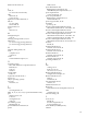
the following table provides two sample origin and destination addresses:
DefinitionRoutingAddress
InfiniBand Switch 1, Port 01OriginIB-SW1-P01
Server 1, InfiniBand HCA Port 0DestinationServer1-IB-P0
F.2 InfiniBand Cabling Tables for Rack-Mountable Servers 121