
Workgroup System and Cluster Platform Express Overview and Hardware Installation Guide


If more than one interconnect is present, they are joined together in a federated configuration.
A typical cabling example of the federated cabling for two interconnects is shown in the following
table:
Uplink PortsDownlink Ports
21 – 249 – 12
In the cable labels, or cabling tables, you will see that both the origin and the destination for these
federated link cables is an ISR 9024 port, such as IB-SW1-P24 to IB-SW2-P24.
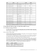
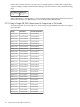
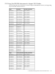
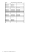
F.2.2 Using a Single ISR 9024 Interconnect to Support up to 24 Nodes
The following table shows the links for a cluster using a single ISR 9024 interconnect to support
up to 24 nodes.
Secondary DestinationDestinationOrigin
Server24-IB-P0Server23-IB-P0IB-SW1-P01
Server23-IB-P0Server22-IB-P0IB-SW1-P02
Server22-IB-P0Server21-IB-P0IB-SW1-P03
Server21-IB-P0Server20-IB-P0IB-SW1-P04
Server20-IB-P0Server19-IB-P0IB-SW1-P05
Server19-IB-P0Server18-IB-P0IB-SW1-P06
Server18-IB-P0Server17-IB-P0IB-SW1-P07
Server17-IB-P0Server16-IB-P0IB-SW1-P08
Server16-IB-P0Server15-IB-P0IB-SW1-P09
Server15-IB-P0Server14-IB-P0IB-SW1-P10
Server14-IB-P0Server13-IB-P0IB-SW1-P11
Server13-IB-P0Server12-IB-P0IB-SW1-P12
Server12-IB-P0Server11-IB-P0IB-SW1-P13
Server11-IB-P0Server10-IB-P0IB-SW1-P14
Server10-IB-P0Server9-IB-P0IB-SW1-P15
Server9-IB-P0Server8-IB-P0IB-SW1-P16
Server8-IB-P0Server7-IB-P0IB-SW1-P17
Server7-IB-P0Server6-IB-P0IB-SW1-P18
Server6-IB-P0Server5-IB-P0IB-SW1-P19
Server5-IB-P0Server4-IB-P0IB-SW1-P20
Server4-IB-P0Server3-IB-P0IB-SW1-P21
Server3-IB-P0Server2-IB-P0IB-SW1-P22
Server2-IB-P0Server1-IB-P0IB-SW1-P23
Server1-IB-P0Control-IB-P0IB-SW1-P24
122 Cabling Tables for Rack-Mountable Servers