
Workgroup System and Cluster Platform Express Overview and Hardware Installation Guide
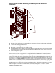
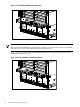
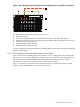
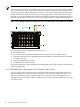
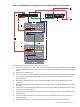
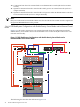

Figure 1-12 CP Workgroup System Configuration with Single-Density Server Blade Control Node
1
5
2
3
4
The following list describes the callouts in Figure 1-12:
1. HP GbE2c switch
2. Connection from the Onboard Administrator's iLO port to the HP GbE2c port 22
3. Optional connection from a server blade control node through an HP GbE2c external port
to an external campus network.
4. Onboard Administrator module
5. HP BladeSystem c3000 enclosure
See Appendix B for the origin and destination cabling tables for the cables used in CP Workgroup
System configurations.
1.4.6.2 CPE Workgroup System with Double-Density Server Blades
If the control node is a double-density server blade, server 1 is designated as the control node.
NIC2 of server 1 is routed to IMB2 and connectivity to an external network is provided by an
HP GbE2C switch installed in IMB2 in the HP BladeSystem c3000 enclosure. If external
connectivity to a network is not required this switch may be omitted.
Figure 1-13 shows the connection to an external network for a configuration using a c3000
enclosure and a double-density server blade control node.
1.4 CPE Architecture Overview 27