
Workgroup System and Cluster Platform Express Overview and Hardware Installation Guide


B CP Workgroup System Configuration Diagrams and
Cabling Tables
This appendix describes the following topics:
• Example configuration diagrams (see Section B.1)
• CP Workgroup System cabling tables (see Section B.2)
B.1 Example Configuration Diagrams
This section includes the following CP Workgroup System configuration examples:
• CP Workgroup System – basic configuration (see Section B.1.1)
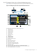
• CP Workgroup System – external control node (see Section B.1.2)
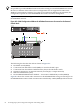
• CP Workgroup System with direct attached storage blade SB40c (see Section B.1.3)
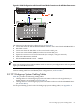
• CP Workgroup System with an optional InfiniBand interconnect (see Section B.1.4)
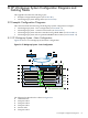
B.1.1 CP Workgroup System – Basic Configuration
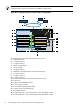
Figure B-1 shows a CP Workgroup System basic configuration.
Figure B-1 CP Workgroup System – Basic Configuration
16
15
1
14
19
2
3
4
5
13
12
11
7
6
10
9
8
17
18
The following list describes the callouts in Figure B-1:
1. c3000 enclosure
2. Compute node 3
3. Compute node 2
4. Compute node 1
5. Control node
6. Compute node 7
B.1 Example Configuration Diagrams 63